January 2026
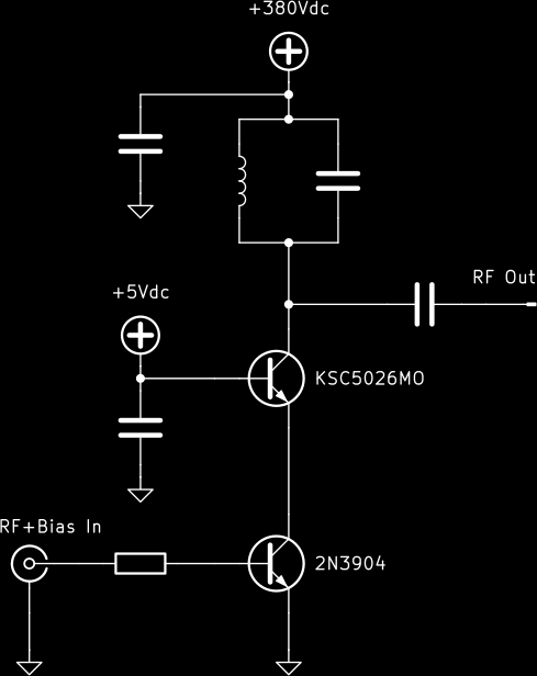
Helical resonators driven by 50-ohm RF amplifiers are often used to provide the high-voltage, high-frequency current necessary for Paul traps. While they are not particularly expensive, they are finicky and cumbersome. It turns out that a simple and low-cost lumped LC resonator driven by a high voltage bipolar transistor can generate many of the RF voltages and frequencies reported in the literature, and with the exception of a simple homebrewed inductor, consists of just a few mass-produced electronic components.
The key point is the high voltage transistor must be operated in a cascode circuit - considering the large voltage swing at the collector, Miller capacitance becomes a serious issue; in a cascode (or more generally common-base) circuit, the collector-base parasitic capacitance simply becomes connected in parallel at AC with the resonator and only lowers its resonance frequency.
A high-grade high-voltage capacitor, typically with NP0 dielectric, must be used for the resonant tank. Regular high-voltage ceramic capacitors are not designed to be charged and discharged millions of times per second. They heat up and cause inefficiencies and major drifts of the resonant frequency; they may even desolder themselves or burn out. I have successfully used the 561R10TCCQ39 (39pF) and 561R10TCCT10 (100pF) from Vishay.
To avoid complications associated with ferromagnetic cores, the coil is simply wound on air.
The transistor amplifier is operated in class C for efficiency; a small DC bias of hundreds of millivolts can be applied at the input to improve harmonic content.
This leads to the schematic below:
Observing the output can be done with a low-cost Hantek T3100 oscilloscope probe. Note the voltage derating curve with frequency, which comes in the included booklet and which I have been unable to find online:
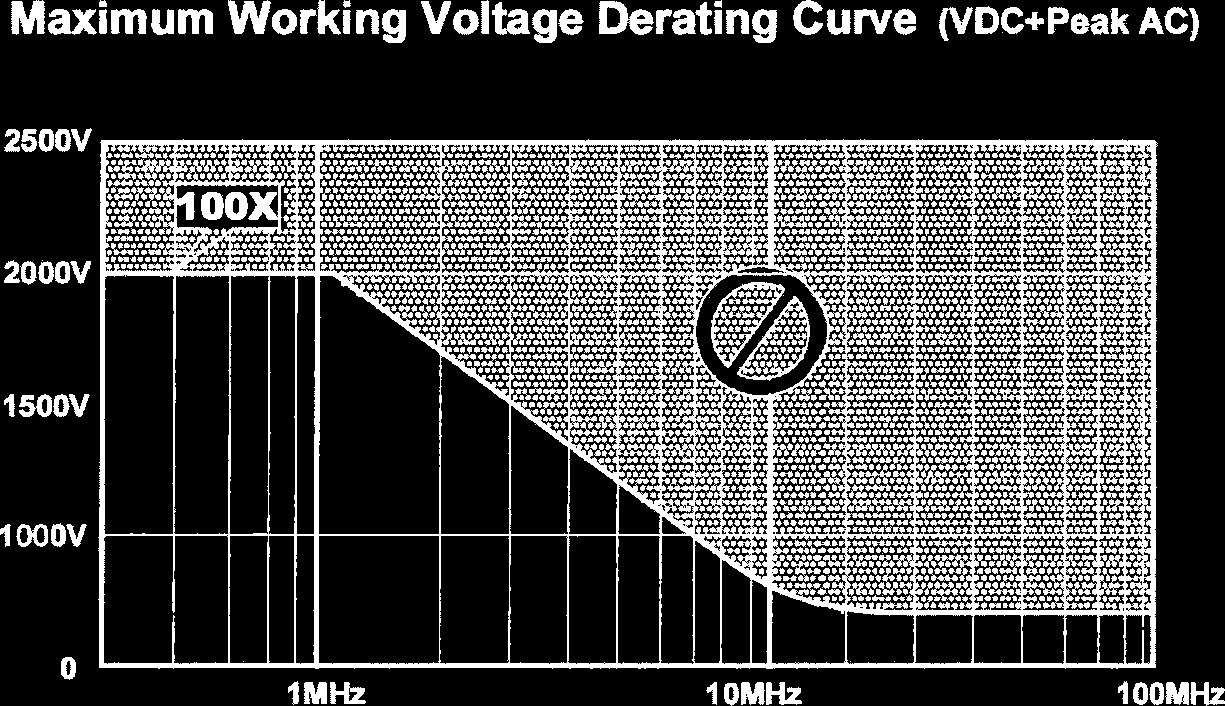
With this circuit, I have been able to produce 3MHz at 730Vpp using 2x100pF capacitors in parallel and a 55-turn coil, and 11MHz at 630Vpp using a 39pF capacitor and a 16-turn coil (matching the RF parameters used in the paper Laser ablation production of Ba, Ca, Dy, Er, La, Lu, and Yb ions by S. Olmschenk & P. Becker). Both coils were tightly wound using 0.35mm enameled copper wire on a 10mm plastic mandrel; they get a little hot and using higher-diameter and possibly silver-plated wire may be desirable. Note that the 11MHz test slightly exceeds the maximum voltage of the T3100 probe at that frequency, but it survived the punishment.
At 11MHz 630Vpp the power draw on the high voltage rail is just under 5W. The stability is not excellent, which together with uncertain high voltage transistor noise may be the weak point of this design compared to helical resonators (or even lumped circuits driven by a traditional RF amplifier with impedance matching). Blowing on the KSC5026 heatsink causes a noticeable change in the resonance frequency which shows up as the amplitude slightly decreasing on the oscilloscope. At 3MHz the circuit is much less sensitive, which is understandable considering the large 200pF tank capacitance.
Unlike traditional systems that step up the RF voltage alone, the presence of the high DC voltage in this circuit makes it an electric shock hazard, so be careful.
KiCad design based on this idea.
> Another ion trap RF source
< Table of Contents