August 2020
In most lasers, the spacing between the modes noticeably deviates from the FSR of the laser cavity. Indeed, the gain medium "pulls" the frequencies of the resonating modes towards the maximum the gain curve, which results in a small detuning from the frequencies that would be expected if the cavity contained vacuum. This phenomenon is easy to observe using a short two-mode HeNe laser tube and a software defined radio. We need the HeNe tube to be short so that at most two modes are oscillating (short tubes have a higher FSR which means that only one or two modes can be under the narrow neon gain curve at any given time). This in turn results in a beat note between the modes at around 1GHz, which is the signal we will be looking at. For information about the workings and procurement of HeNe lasers, see Sam's Laser FAQ.
Direct the beam into a polarizer oriented at approximately 45 degrees relative to the tube's polarization axes (in red HeNe lasers, the modes are polarized orthogonally from each other) and into a silicon photodiode connected directly to the SDR's antenna input. The signal is strong with plenty of room for inefficiencies, so, it does not really matter if the polarizer is not very well aligned, if the photodiode is not a particularly high-speed model, if the SDR's 50-ohm input is not a great photodiode frontend, if your SDR is cheap, etc. If you want a photodiode that is guaranteed to work, the Hamamatsu S5973 is a good choice, though many cheaper ones will also produce a usable signal. Telecom photodiodes for 1310nm/1550nm will NOT work as their semiconductor material is not sensitive to visible light. To increase signal if necessary, you can use a lens to focus the beam onto the photodiode's active area. If your SDR has a bias-T function, it can be turned on to reduce the photodiode's capacitance, but make sure that the photodiode is reverse-biased otherwise damage will occur. An external bias-T can also be used instead and typically can reach higher bias voltages.
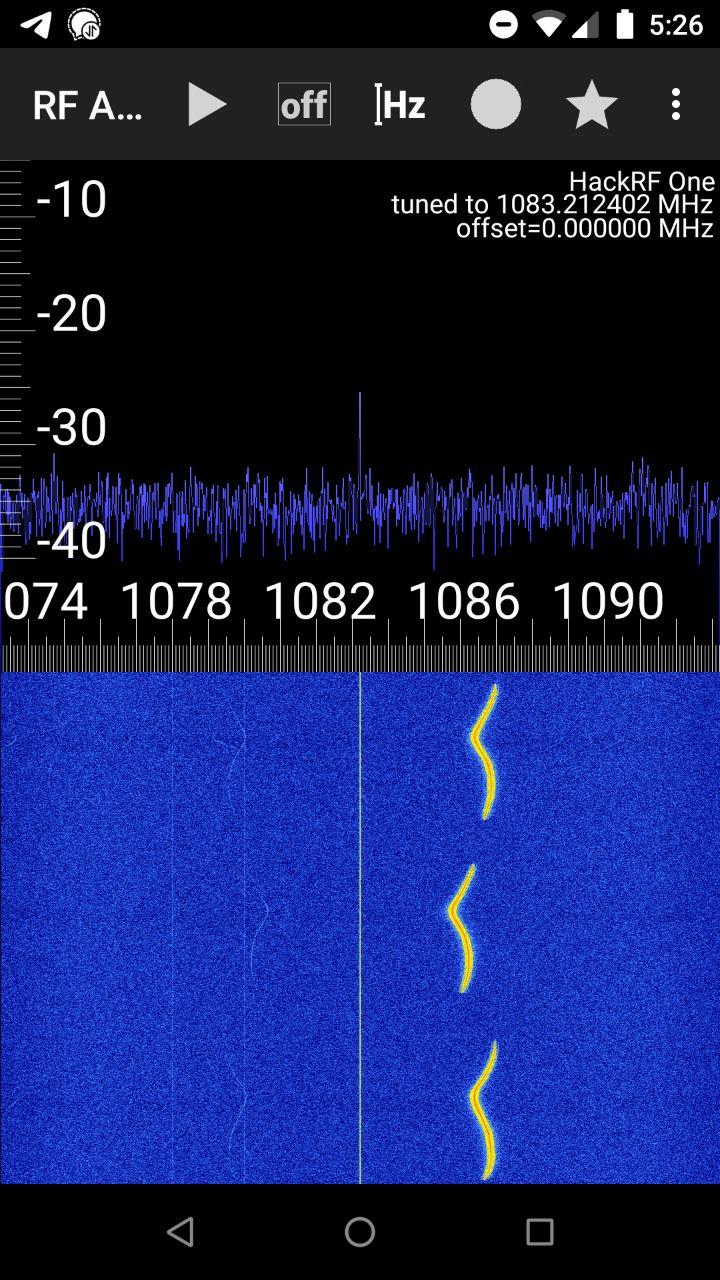
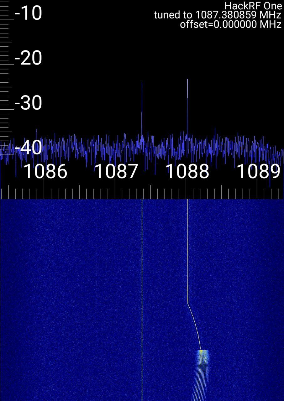
A HeNe tube freshly turned on and warming up will go through cycles of mode sweeping, as its cavity expands from the temperature rising. This causes the cavity modes to move under the neon gain curve, as explained in detail on Sam's Laser FAQ. The frequency pulling effect causes the distance between the modes to vary substantially and non-monotonically (much more than what would be expected from the small and monotonic decrease in the FSR caused by the expansion) and is clearly seen on the SDR's waterfall display. The RF signal also vanishes periodically as the tube crosses into regions of single-frequency operation.
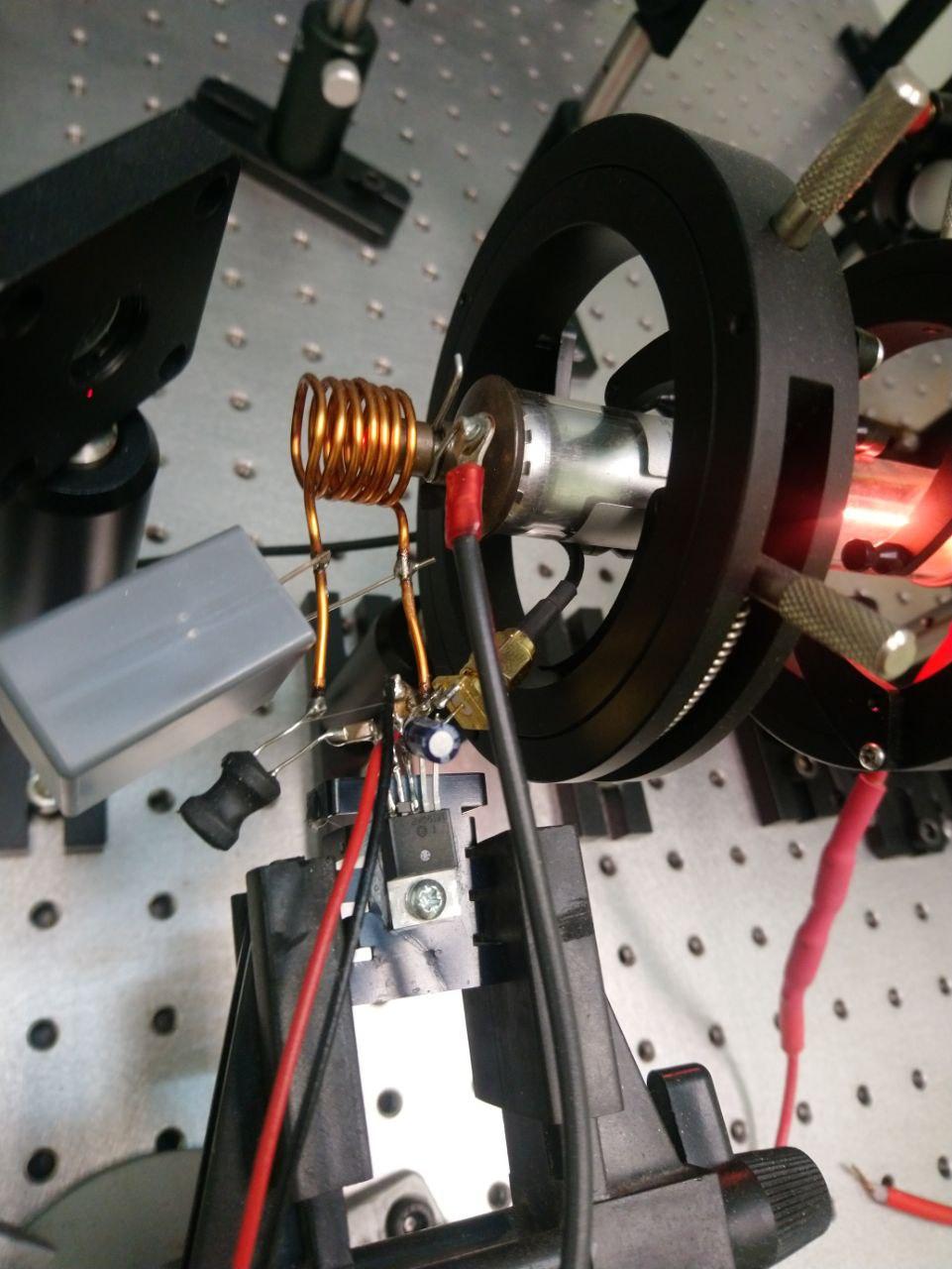
Thanks to frequency pulling, we have information about where the cavity modes fall on the neon gain curve, and we can use it to stabilize the HeNe laser tube. There are multiple ways to control a HeNe cavity length, and many are described in Sam's Laser FAQ. The technique used here is based on a small induction heater with the heating coil that goes around the tube's metallic mirror mount.
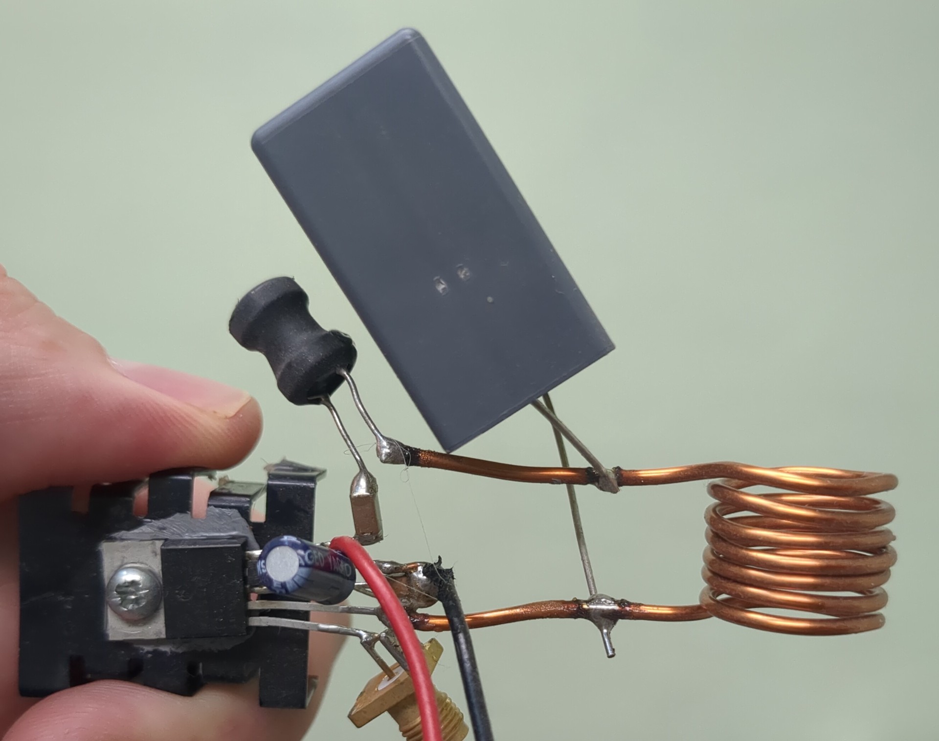
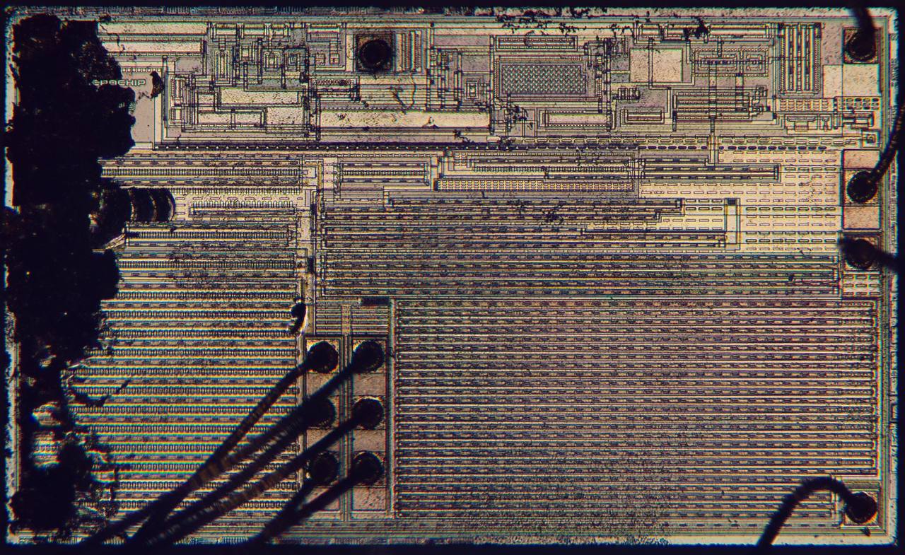
The induction heater (see detailed circuit photo) is simply a MCP1407 MOSFET driver which feeds a resonant LC tank through a series inductor. External MOSFETs are not necessary as the MCP1407 itself can already provide enough power to make the HeNe tube go through dozens of cycles of mode-sweeping. The power delivered to the mirror mount can be varied by taking the LC tank further from or closer to resonance by changing the drive frequency. This is accomplished by connecting the input of the MCP1407 to a low-cost MHS5200A function generator that can be controlled over USB. This method is very power-efficient (the heatsink seen on the pictures is not really necessary) and does not need a DAC. The LC tank capacitor must be one specified for induction heating applications; general-purpose capacitors are not designed for being constantly charged and discharged hundreds of thousands of times per second at high current and they will heat up and burn (the current circulating in the tank is much higher than the 6A that the MCP1407 can supply!). Additionally, external protection diodes that clamp to the power rails must be added on the output pin of the MCP1407. Otherwise, if the circuit is powered down with the tank at resonance, the stored energy will discharge into the MCP1407 and cause part of its die to literally explode (Photo: Sascha Naske). Also, beware that the HeNe tube's electrodes may be at a very high electrical potential (it can be in excess of 10kV before the tube strikes), and design things so that the tube's mirror mount won't arc to the heater coil (for example, ground the tube's cathode and install the heater coil there - study your HeNe power supply to check if this solution would work).
A software-based P controller that adds an offset to the induction heater's drive frequency proportional to the difference between the beat note between the modes and a reference value is sufficient to lock the laser. After trying a few algorithms for lock acquisition and not being very successful at making them reliable, I simply added a second offset to the drive frequency which is chosen randomly when the laser lock times out after a few seconds. This may not be the fastest or most beautiful technique but it is simple to implement and pretty foolproof.
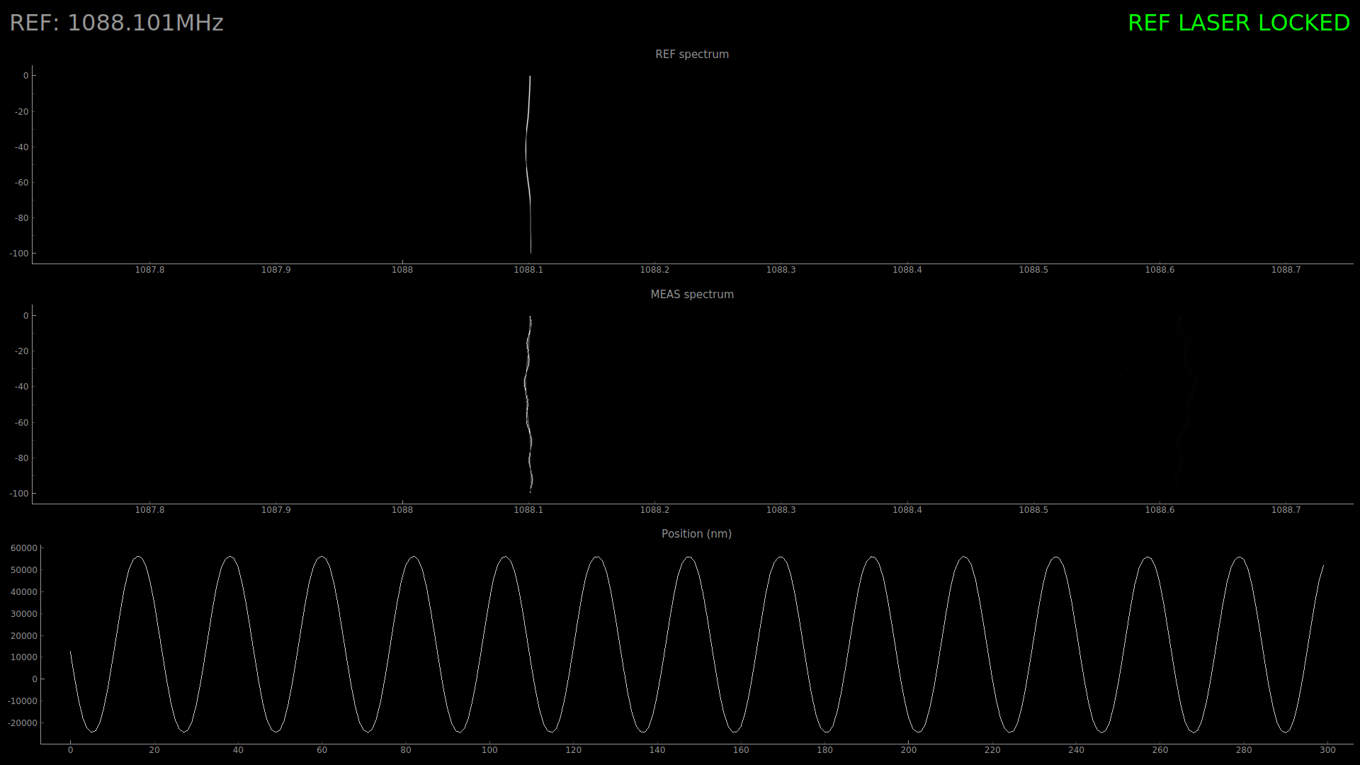
With the laser stabilized in a two-mode region and the mode beat ("REF") signal already digitized by the SDR, all that it takes to build a DMI is to follow the techniques for the two-frequency interferometer described on Sam's Laser FAQ with just that different laser source and a SDR to process the signals. Without the Zeeman split, the tube already emits two orthogonal linear polarizations so the waveplates are not necessary. You need a two-channel coherent SDR for this experiment, such as the bladeRF. With complex (IQ) samples such as those acquired by the bladeRF, the displacement is proportional to the unwrapped argument of the MEAS signal multiplied pointwise by the conjugate of the REF signal. This computation can be implemented with just one line of Python/NumPy code :)
The results are seen in this screenshot, with the moving corner cube mounted on a speaker driven by a sine wave. I have not attempted to quantitatively characterize it or optimize it, but the system subjectively seems a bit noisier than the Zeeman-split ones from HP. Nevertheless, displacements can be tracked with about a dozen nanometer accuracy.