April 2023
The Pound-Drever-Hall method is a common and powerful technique to lock cavities to lasers and lasers to cavities. For example, a "transfer cavity" can be locked to a reference laser using one PDH control loop that tunes the cavity, and then another laser can be locked to the same cavity using a second PDH control loop that tunes the laser. This results in the optical frequency of the second laser being stabilized to the optical frequency of the reference laser, plus or minus an integer multiple of the cavity's FSR.
Another example which is conceptually simpler (but rather painful in practice due to phase-matching problems, cavity mirror alignment issues, and expensive optical coatings) is to build up optical power from a laser into a resonant cavity that contains a nonlinear crystal, which takes advantage of the facts that nonlinear crystals are more efficient at high power levels and that most of the light which isn't converted simply goes through the crystal unchanged. This dramatically increases the efficiency of the nonlinear process, at the expense of a very substantial increase in complexity and cost.
Lastly, in optical clocks an ultra-stable cavity is often used as a "flywheel", through application of the PDH process, to keep the frequency of the clock laser extremely stable between the interrogations of the atomic reference, which can be spaced by several seconds.
A detailed description of the PDH technique can be found in the very good paper "An introduction to Pound-Drever-Hall laser frequency stabilization", by Eric D. Black of the LIGO collaboration.
The PDH technique can also be used with a very inexpensive fiber ring resonator. While it obviously won't detect gravitational waves, it is more than a cute demonstration. It could in theory be used to reduce the linewidth of a DFB semiconductor laser via electronic feedback, or perform resonant pumping of a stimulated Brillouin scattering laser and dramatically increase its efficiency (up to 50% is theoretically possible). The transfer cavity application mentioned above is also possible, with the caveat that dispersion in the fiber has to be taken into account if the absolute optical frequency of the locked laser is to be known precisely. The shape of the error signal is not exactly the same as with conventional two-mirror resonators, but it is very similar and possesses the key property of odd parity about the cavity's resonance peak, which is what makes feedback loops possible.
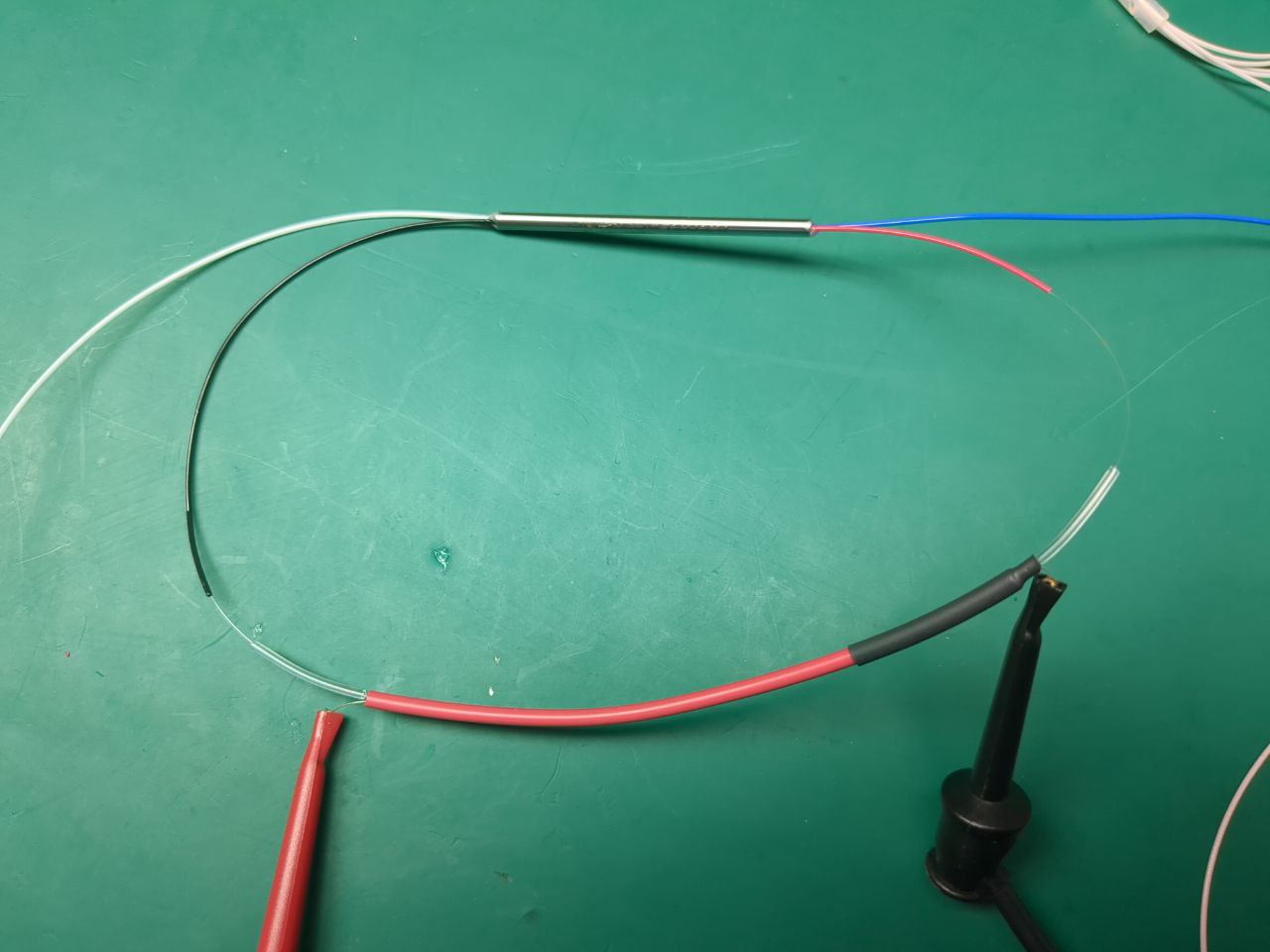
The fiber resonator is formed, just like in the previous article, by splicing two ports of a 2X2 FBT splitter and using a polarization controller to align the incoming light with the birefringence axes of the resonant fiber loop. While the PDH technique could be demonstrated by tuning the laser alone using its TEC, this experiment is a good opportunity to also demonstrate a simple trick for tuning fiber ring resonators. Before the resonator is spliced, take a dozen centimeters of multi-strand silicone electrical wire, and strip both ends over 1-2 cm. Then remove all copper strands except one which will be used as a resistive heater, and pass the bare optical fiber that will form the resonator into the wire's insulation together with the remaining strand. Silicone insulation makes it easier to remove all the strands over a relatively long section of cable, and is also a better thermal insulator. An example of wire to use is RS 359-683. Splice the fibers, and slide the splice into the wire's insulation to provide some protection. Note that the splice point will remain fragile and bending the fiber should be avoided as much as possible in this area (which is why splice protection sleeves contain a rigid metal bar), though the moderate bending from the resonator loop will typically be OK. If you are building a long resonator with a small FSR, you can of course protect the splice with a traditional sleeve and place the heater somewhere else. Hold things in place using heat-shrink tubing, which of course had to be inserted prior to splicing. The result looks like this and passing a few amperes into the remaining copper strand heats the fiber and causes the resonator to sweep over many FSRs.
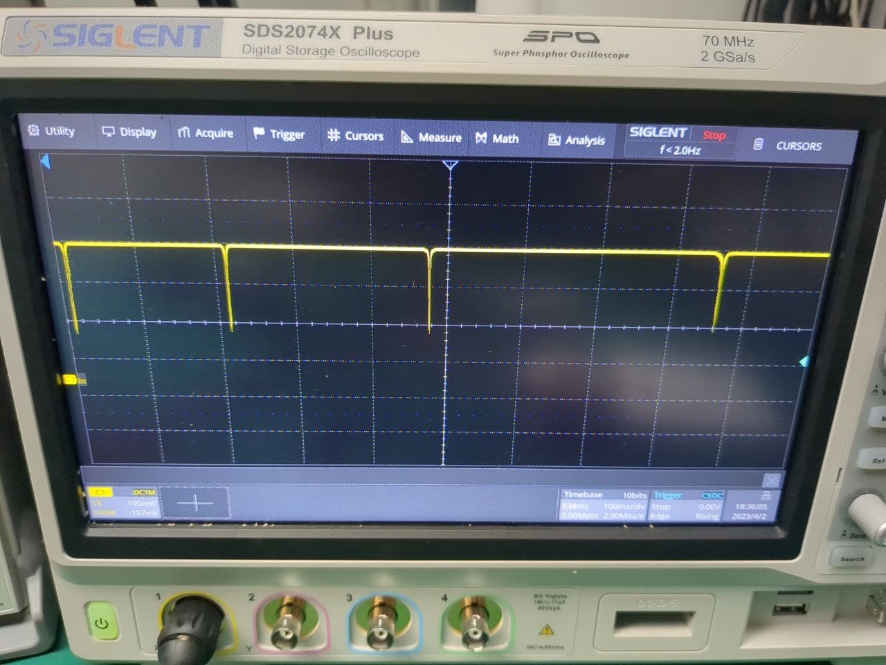
The sidebands for PDH can be produced by injecting RF into the drive current of the DFB laser diode, which avoids using an expensive EOM (but it is very difficult to get rid of the sidebands afterwards, which can be a problem in some applications). Only a very small amount of RF power is required, but one must be careful that electrical noise from the RF generator does not reach the laser. Coupling both ground and signal using capacitors of a small value is a simple solution that helps cut low-frequency noise and eliminate ground loops; alternatively, one can build a simple RF isolation transformer with a few turns of enameled wire on a piece of plastic. Efficiency may be terrible with those solutions, but the power is so low that it does not really matter. Tune the RF power while scanning the cavity (repeatedly turn the heater on and off) so that small sidebands appear on each side of the resonance peaks.
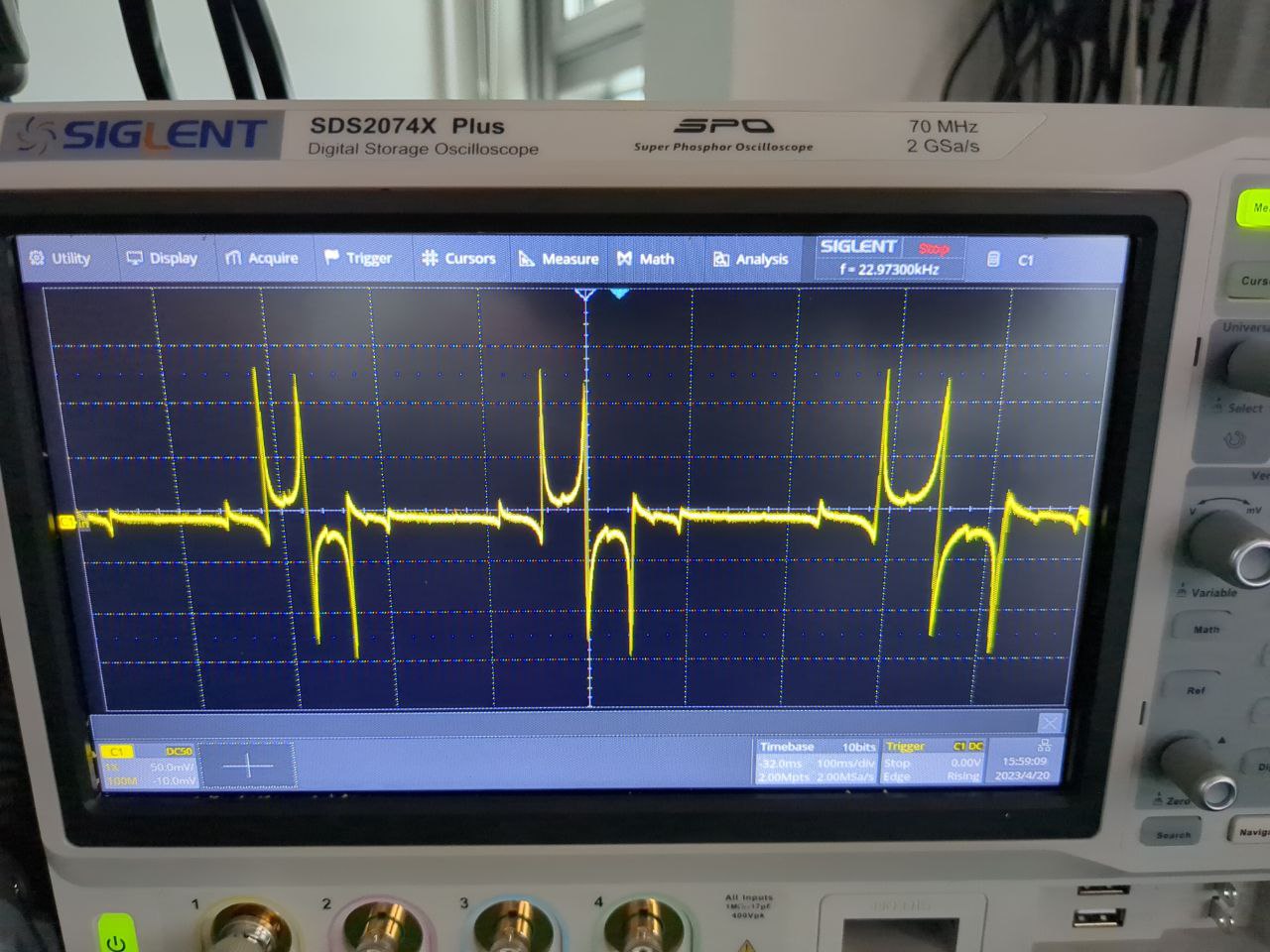
Once this is done, the PDH error signal can be easily observed. The curve shows some irregularities which are related to polarization issues (orthogonally polarized mode resonating at the same time with a slighly different FSR from the birefringence); they can be reduced with (tedious) adjustment of the polarization controller and probably by using PM fiber and the associated expensive splicers. Those irregularities are far more visible on the PDH error signal than on the intensity plot. This signal was demodulated with a somewhat pricy Sinara 4459 Pounder, but it sounds definitely possible to do it on a shoestring using RF modules from Aliexpress/Taobao instead.