June 2026
A previous article described a compact RF source for trapping ions. While conceptually very simple, it requires clean high voltage DC which can cause some difficulties and represents an electric shock hazard, and its maximum frequency and stability at high frequencies are not great due to limitations of high voltage transistors.
Another simple and cost-effective solution is to use a resonant pi-network (similar to those in antenna tuners) configured to step up the voltage, which completely removes hazardous DC from the circuit and allows low-voltage transistors with better characteristics to be used. Tapping a LC resonator's coil does not work very well due to the parasitic capacitance of the transistor, but doing the equivalent operation on the capacitor is fine, as the parasitic capacitance is simply paralleled - which is what a pi-network does.
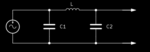
You can see the step-up pi-network as a LC resonant circuit where the capacitor has been replaced with a capacitive divider, with energy injected into the resonance at the low-voltage point of the divider. With the ground in the middle, the voltage gain is C1/C2. One advantage of keeping the ground in the middle is that any trap DC can be directly injected on the low-voltage side of the resonator, making C2 and L the only high-voltage parts in the entire system.
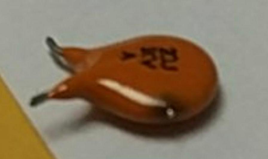
As before, very high quality capacitors must be used in this circuit so that nothing ends in flames. I have used two K102J15C0GF53H5G in parallel (2nF total) for C1 and a 561R10TCCT10 (100pF) for C2. The inductor L was made by tightly winding 14 turns of enameled copper wire of 1mm diameter on an acrylic tube of 16mm diameter. It is necessary to use thick copper wire as the resonant current reaches a few amperes, and the coil gets hot (unfortunately, the skin effect means that most of this copper does not carry current, so much thicker copper is necessary compared to DC). The coil was then coated with EPO-TEK 353ND epoxy to make it less sensitive to vibrations that would change its inductance and make the resonance frequency wobble. Using such an advanced adhesive (high-strength, heat-resistant and vacuum-compatible) for this purpose is completely overkill, but when purchased by the bottle on the Chinese grey market it is cheaper than the hardware store stuff, and required elsewhere for vacuum chamber reasons :) Using silver-plated copper wire does not noticeably improve performance, and it is harder to procure and harder to use as there is no enamel.
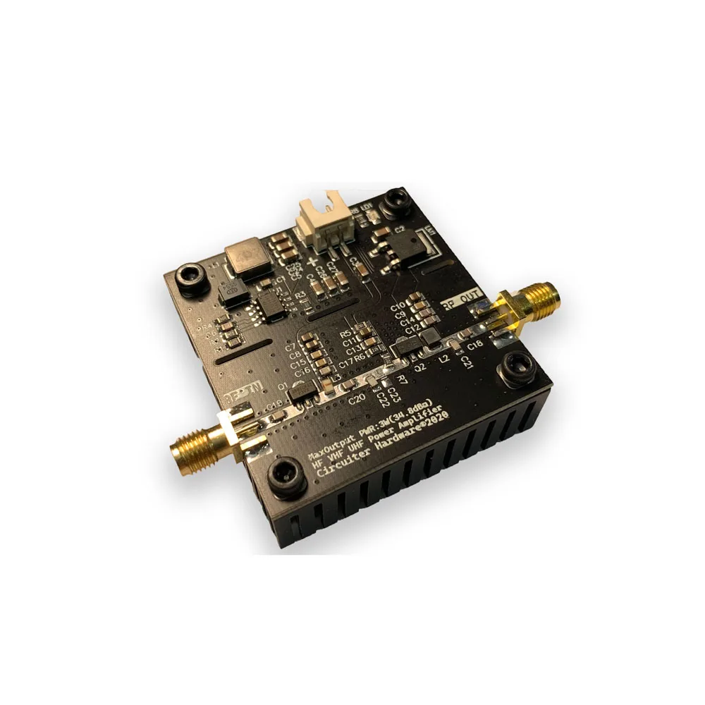
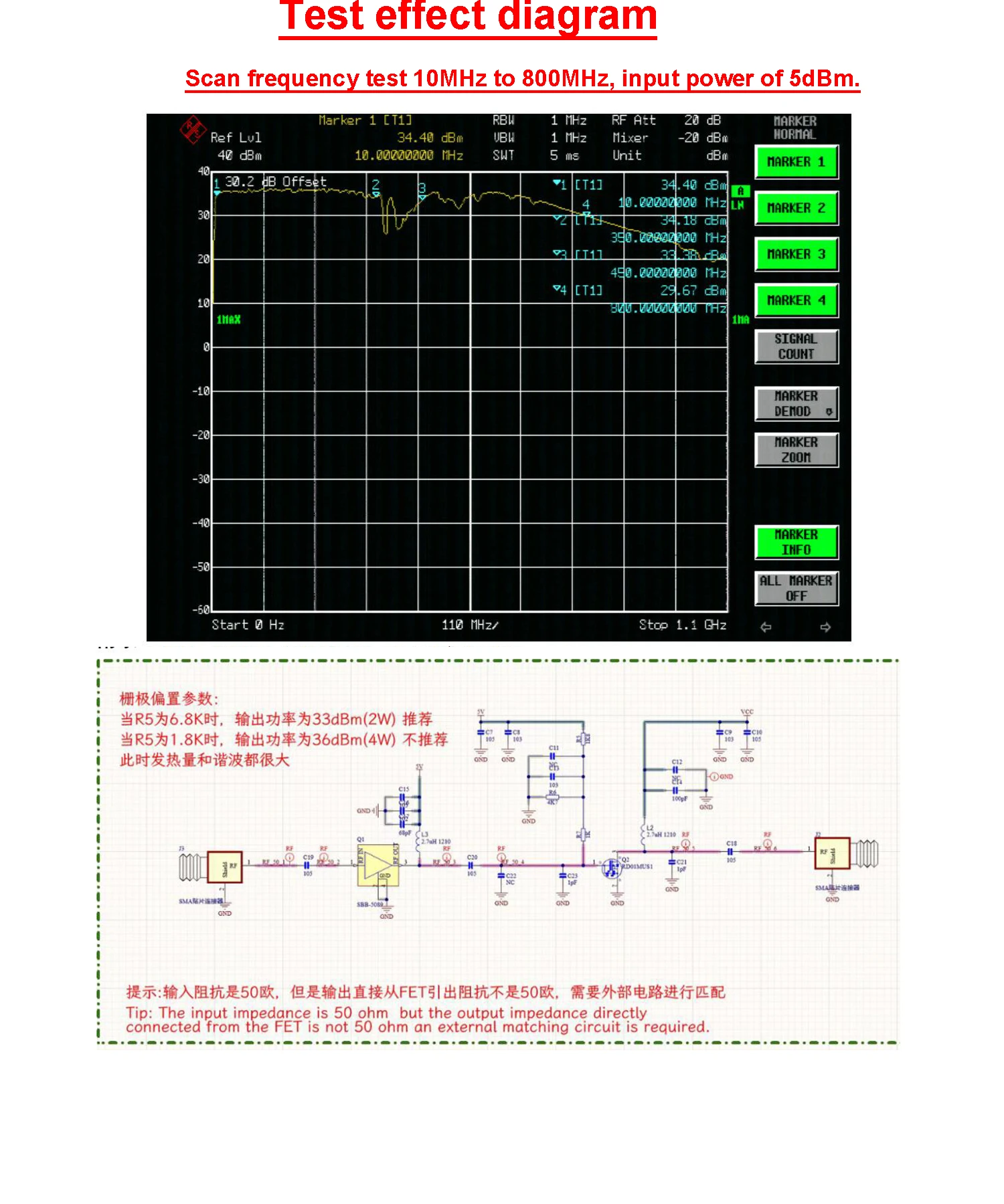
This circuit was driven at 11MHz by a cheap'n'nasty "Circuiter Hardware HF VHF UHF Power Amplifier" from Aliexpress (picture, schematic), supposedly capable of putting out 4 watts between 0.5MHz and 800MHz - in reality under ideal impedance matching conditions only, not for long periods of time before the output transistor blows up, and possibly with one or both active RF parts being driven beyond their ratings. Adding thermal paste between the PCB and the heatsink and making sure the power MOSFET's source terminal is properly soldered takes those amplifiers a little closer to their advertised specifications. The pi-network was directly connected to the amplifier's output with a short coaxial cable, which under the operating conditions behaves like a capacitor simply added in parallel to C1.
Obtaining over 630Vpp at 11MHz was straightforward while staying within the (actual) safe operating area of the low-cost RF amplifier, and with better stability than the previous circuit based on a high-voltage transistor. Thanks to the large value of C1 (and to a lesser degree the smaller capacitance of lower-voltage transistors), changes in the parasitic capacitance of the transistor due to temperature have a much smaller effect on the resonance frequency of the circuit.
Holding a neon indicator bulb near the high voltage output causes it to light up, as would happen with a Tesla coil.
The "NWDZ RF_PA V2.0" is also very low-cost and perhaps a better alternative to the "Circuiter Hardware" module, as it does not contain a switch-mode converter for the RF output stage power supply. The concern is the switch-mode converter can put out noise on the supply rail, which would go through the circuit and cause ion heating.
This circuit was inspired by studying the image current detection system tersely described in Hans Dehmelt's fantastic 1969 paper "Hyperfine Structure of the Ground State of 3He+ by the Ion-Storage Exchange-Collision Technique". More on such techniques can be found in the PhD thesis "Storage and radiative cooling of light ion gases in radio-frequency quadrupole traps" by David Church. Despite being mentioned on nobelprize.org, a copy of that thesis was hard to obtain until now.
> Compact Ion Trap Radiofrequency Source
< Table of Contents