February 2023
The 2025 upgrade of this experiment is at the same time simpler, cheaper, and much more powerful. With care and a bit of additional instrumentation, the 2025 design may even outperform the original paper in terms of accuracy. You should follow the 2025 design instead of the one below, many parts of which are now obsolete.
A few months ago I came across the paper Optogalvanic spectroscopy of the hyperfine structure of the 5p65d2D3/2,5/2 and 5p64f2Fo5/2,7/2 levels of La III. Like almost every experimental atomic physics paper, it involves wanton use of expensive and annoying laser equipment such as a ECDL, FPI and BOA. However, it occured to me that superior optical telecommunication components are available at the wavelengths involved, which could make for an interesting replication. This article broadly describes the procedure as well as practical tips to sucessfully complete it.
The manipulation of ion and neutral atom qubits, including laser cooling, requires lasers with excellent absolute wavelength accuracy and stability. Spectroscopy is a common way to tune and verify such lasers. In the case of optogalvanic spectroscopy, the target ion species itself is often used as the wavelength reference. While there are multiple difficulties with doubly-ionized lanthanum that are not present with conventional ions, it can in theory be used as a qubit directly.
The laser is a "butterfly" DFB module from Shenzhen Box Optronics intended for CWDM telecommunications with fiber coupled output. Center wavelengths of 1410nm and 1390nm at 25C are semi-standard and near the La III wavelengths of interest. Nominal output power is 10mW. Thanks to the DFB technology, the lasers have single-frequency output and the frequency can be tuned via the integrated TEC, over a large range and without any of the nasty behavior exhibited by FP diodes and ECDLs. The modules also integrate a monitor photodiode and thermistor. The linewidth is not specified, but I have measured it to be below 10MHz, which is more than good enough for this experiment. While this may come as a surprise to people who are used to paying ridiculous prices to certain laser companies, it appears that many semiconductor lasers have linewidths in the ballpark of MHz or dozens MHz, including the diode of a $5 laser pointer if you can operate it in a single-frequency region.
The laser is simply driven with a two-channel lab power supply connected to the diode with a current-limiting resistor, and to the TEC. It is important NOT to drive the laser directly from the lab power supply in constant-current mode without the resistor. Many lab power supplies contain a decoupling capacitor which could charge to the full voltage limit, and then discharge into the diode when it is connected and damage it. Laser diodes have much less tolerance for current spikes than LEDs. So the power supply must be operated in constant-voltage mode instead, and with a resistor in series with the laser to "smooth" the response and make the current easy to control.
It is also a good idea to use a high-quality power supply and, before connecting the laser, test it for output voltage spikes particularly when it is switched on and off and when the controls are changed (note that laser diodes do not like reverse polarity either). Or just invest in a proper laser driver ;)
If you are operating the laser near its maximum rated output power, it is important that said maximum power be never exceeded, not even for a short time. This is harder than it sounds for two reasons: (1) laser diodes are more efficient at lower temperatures, and (2) the diode heats up as current goes through it. This means that if you run the laser at a current level that is safe, then turn it off for a few seconds and allow it to cool down, then suddenly apply the same current again, the laser would briefly produce more power and can become damaged. Only using a temperature controller on the butterfly package may NOT be enough depending on the operating conditions of the laser and how close you are to the damage threshold, because of the thermal resistance and thermal lag between the different components of the butterfly package. This is why good laser drivers have an option to ramp up the diode current over a couple hundred milliseconds when they are turned on. Another thing to be aware of is that the laser power will increase as you use the TEC for cooling during wavelength sweeps. So you basically have three options: (1) operate the DFB at, say, 50% to 75% of its rated power to keep ample safety margins (this will increase its linewidth, but it is well below the Doppler broadening in the HCL) (2) keep an eye on the laser power (low-cost multimeter in ammeter mode on the monitor photodiode is enough) as you slowly change the operating conditions of the laser, or (3) use a good laser driver which automatically takes care of those problems.
The original paper uses a free-space Fabry-Perot interferometer that gives a pulse every time the optical frequency crosses a 500MHz boundary, which is very useful to monitor the variations in optical frequency, as well as verify the correct operation of the laser. Obviously we do not want to use such an annoying device, which is expensive, fragile (I have one which developed mirror rot due to the high air humidity in HK), and finicky to align. It is much better to take a 2X2 FBT splitter costing less than a dozen dollars and splice two ports together to make an all-fiber ring resonator. A ratio of 90:10 gives a suitable finesse for this experiment with sharp peaks not overly affected by the laser linewidth, and a fiber loop length of about 40cm gives a FSR of about 500MHz as in the original paper. Fusion splicing can be done with a low-cost kit from China - I used the JIC Fiber T-808S available at a fraction of the cost of a Thorlabs SFPI. A high-quality mechanical splice might perhaps work instead, but the higher splice loss would broaden the peaks.
The main difficulty comes from the birefringence induced by the fiber being bent in the loop, which can cause unwanted resonance peaks or no resonance at all. This can be solved by using an inexpensive three-loop polarization controller (available from Box Optronics as well as several shops on Aliexpress and Taobao) connected right before the fiber resonator, and fiddling with it while the laser wavelength is being swept until the peaks look clean on the oscilloscope display. All fibers leading to the resonator should be held in place using tape and a solid plate (I am using a small low-cost aluminum optical breadboard from China, which also holds the HCL and its fiber interface) in order to keep the polarization stable. It is much easier to find a suitable position for the polarization controller's loops than align a free-space FPI.
After the PC is adjusted, turning up the TEC and watching a long series of perfectly regular peaks scroll on the oscilloscope display is very satisfying, especially if you have spent some time attempting the same with a ECDL and free-space FPI.
Calibrating the FSR can be done with a technique similar to the one described in the original paper, however an expensive optical phase modulator is not necessary as you can instead inject RF into the DFB current and then similarly adjust the RF frequency to overlap the sidebands with the resonator peaks.
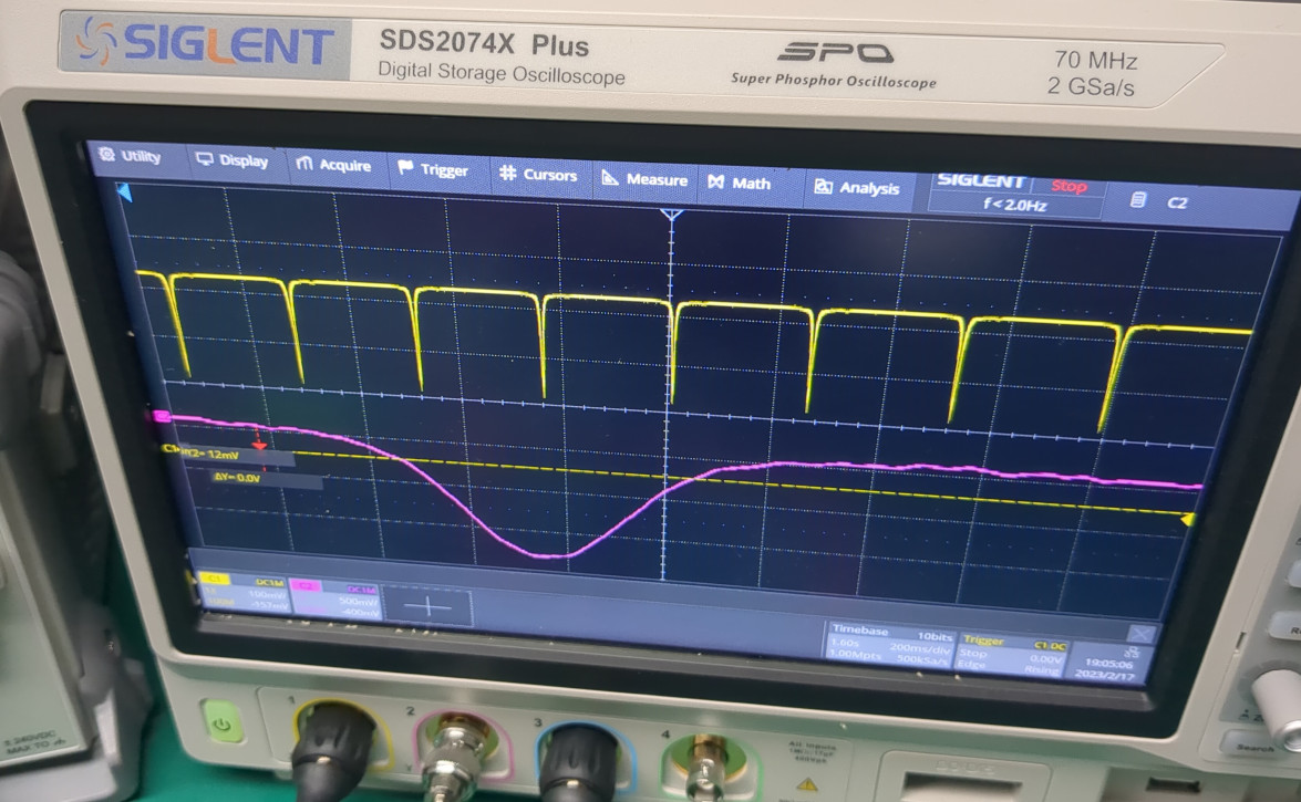
As in the original paper, the HCL is a Photron P827A. Compared to the standard P827 model, it is filled with argon instead of neon and slightly more expensive. The argon fill has two advantages: (1) according to the original paper, it gives better signal-to-noise ratio than neon (2) there is a strong well-documented neutral argon line at 1409.36nm. The Ar I line is easy to see and very useful to demonstrate that your setup is working at all - with the laser tuned on the line, you can wave a piece of paper in front of the HCL window and see the output vary, which gives clear evidence that what you are observing is indeed the optogalvanic effect. The La III signal is much weaker and can be more easily missed. The Ar I line can also be used as a wavelength reference; you can count the fiber resonator peaks from it and know when to expect the La III signal.
To couple the beam from the fiber into the HCL, it is first collimated and launched into free space with a small fiber-fused lens from Box Optronics. It is then reflected off two aluminum first-surface mirrors on kinematic mounts to provide adjustments in all four degrees of freedom. Depending on your mechanical skills, there may be a better way to do it. Those collimation lenses are not ideal - they produce a small beam diameter which diverges fairly rapidly, so you need to pack the HCL, mirrors and lens close together to minimize the distance that the beam travels and spreads. An alternative could be to use a collimation tube with a SMA905 connector (note that FS.com can provide SMA905 patch cables if you ask), which can either be purchased from Taobao or Aliexpress, or made yourself by gluing the shell of an electronic SMA connector to the collimation part of a disassembled laser pointer. Unlike the Box Optronics lenses, these options do not provide AR coating for NIR wavelengths, which may or may not be a problem.
The 1410nm and 1389nm wavelengths are completely invisible, which poses a bit of an alignment challenge. NIR viewers and cameras are always expensive and often poorly performing (you are basically paying five digits for a miserable 0.08 megapixel camera), so I do not recommend using those. Instead, you can simply couple a "visual fault locator" (VFL) red laser (FS.com, Aliexpress, Taobao, and also included with many fusion splicing kits) into the fiber and perform the alignment using that. You can verify with a beam card that the chromatic aberration is not excessive (note that most upconverting beam cards can do 1550nm but not 1410nm/1389nm, however some of the other "light charging" beam cards can work). For this, it helps to use the VFL in blinking mode, and combine both beams with a PLC splitter (unlike the FBT type, they can be used satisfactorily with visible light).
There are cheap HCLs available on Taobao and Aliexpress, however when trying one I could not get any optogalvanic signal out of it, and lanthanum lines were only faintly visible in its output with a grating spectrometer, whereas they were very clear with the Photron lamp. I do not know if this a one-off quality issue or if those lamps are generally bad - a similar low-cost calcium HCL from China gave me strong Ca lines on the grating spectrometer. More data points welcome :) They are also filled exclusively with neon in any case, and their construction does not look as nice as Photron.
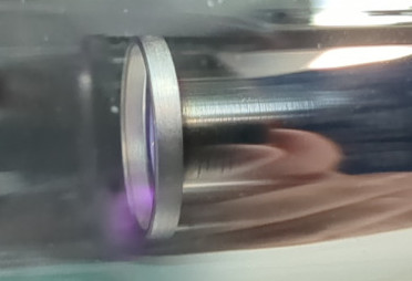
One problem with the HCL is it may produce a strong oscillation at startup, of about a dozen volts (across the 10k anode resistor as in the original paper) and with a frequency of several hundred Hz to several kHz. This oscillation saturates the lock-in amplifier and renders it unusable. The oscillation appears to be accompanied with a plume of plasma over the lamp's anode, as shown on this picture. It appears the solution is to warm up the lamp at high current (25mA) for about 10 minutes, during which the oscillation diminishes in frequency, becomes intermittent, and finally disappears. It does not reappear after the lamp current is lowered. Using an oscilloscope, monitor the HCL's AC signal after the coupling capacitor to check for this problem.
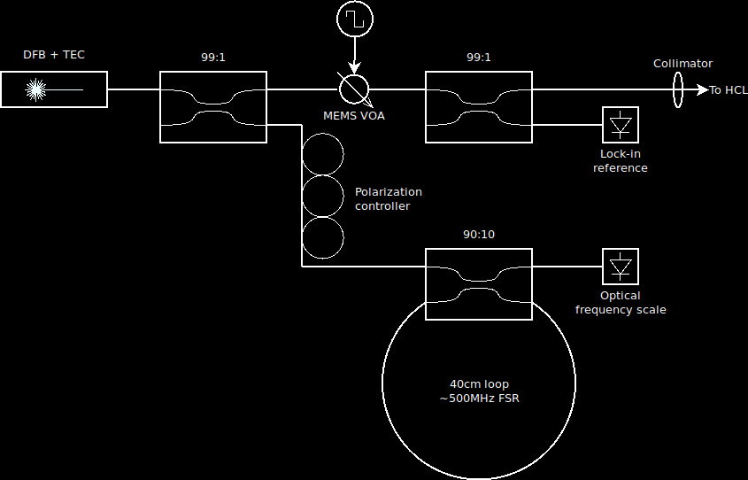
The entire optical layout is as follows:
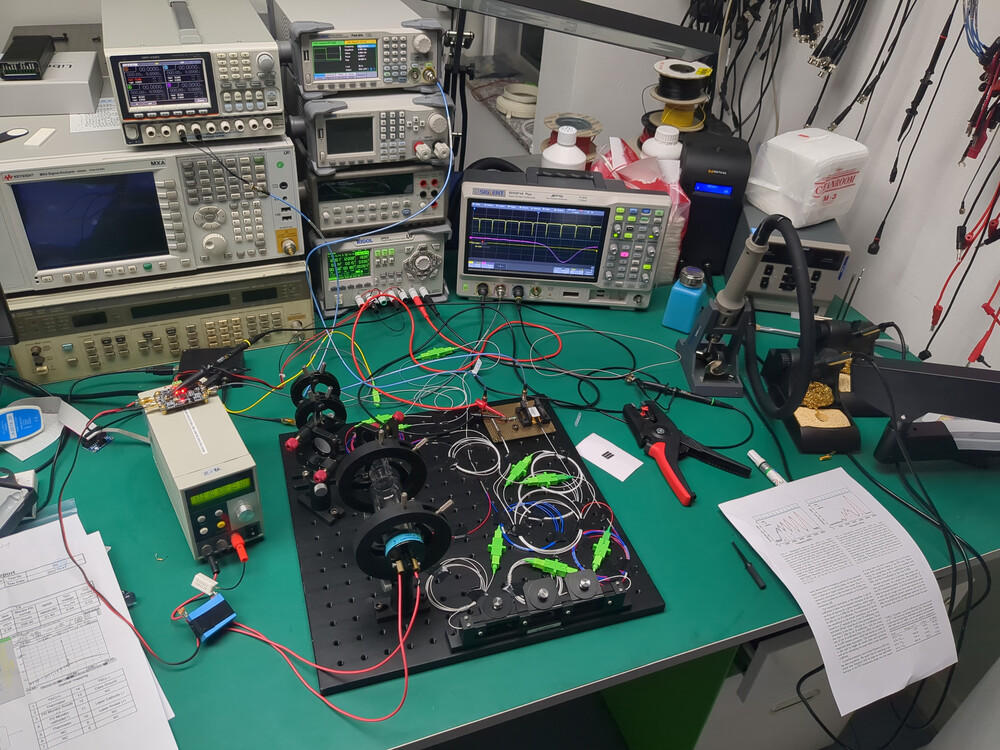
The implementation may look like this (oscilloscope showing the fiber resonator output and the lock-in amplifier output while going over the strong Ar I line).
Fiber splitters with various ratios can be obtained inexpensively from Box Optronics or from various sellers on Taobao. Testing them with an optical power meter (FS.com) showed that they work well enough at 1410/1390nm despite being designed for 1550/1310nm.
In place of the mechanical beam chopper from the original paper, a MEMS variable optical attenuator (VOA) from FS.com is used. This keeps the experiment free from large moving parts and keeps the laser beams in fibers and everything "plug and play" as much as possible. They are not intended for amplitude modulation but they can still be used up to several hundred Hz. Compared to a Mach-Zehnder modulator, the VOA has lower insertion loss and lower cost, but also much slower response time. A photodiode after a second fiber splitter can be used to adjust the VOA drive waveform for maximum contrast and to provide a reference to the lock-in amplifier (see below).
Components are connectorized with SC/APC. The main reason for this is adapters, patch cords, and other components are available with this connector from FS.com with high quality, point-and-click ordering, short lead time, and low price. Many suppliers for other components (photodiodes, laser, splitters, ...) offer SC/APC connectorization at no additional cost. FC/APC is a more common choice for laboratory laser equipment and only slightly more expensive - if you already have FC/APC gear around, you may want to choose that instead.
The lock-in amplifier is an inexpensive "Modem AD630" board from Lockzhiner Electronics (schematics, manual). It consists of a AD620 amplifier, followed by the AD630 demodulator and a low-pass filter based on a NE5532. Several similar boards from other suppliers exist and can be found on Aliexpress and Taobao. While the performance of this gadget applied correctly can rival that of much pricier instruments, its use is not straightforward and there are several pitfalls that must be avoided - which is not difficult nor expensive when you are aware of them.
First of all, the "Modem AD630" is incapable of quadrature demodulation. This means that the reference and input signals must be in phase. This is an issue in our setup as the response time of the MEMS VOA is not negligible compared to the period of the modulating waveform, and the VOA introduces substantial phase shift. This is solved by using a second 99:1 splitter to sample the beam after the VOA and direct a small portion to a photodiode, which provides the required in-phase signal compensated for the VOA response time. The reference input of the "Modem AD630" expects an AC signal and is a bare floating IC input. To interface it correctly, the bare photodiode is loaded with a 10k resistor, followed by an AC coupling capacitor, and a 100k pull-down.
The second issue is the AD620 input stage can saturate. You'll want to power the board near its maximum rated voltage (e.g. +/-12V) to prevent this from occuring and extend the dynamic range of the amplifier. You'll also want to solder a test point at the output of the AD620 and monitor the signal with an oscilloscope to check for saturation as you adjust the gain pot. At high gain settings, the amplifier may also oscillate by itself. With the HCL powered on and warmed up, adjust the gain for maximum amplitude while staying away from saturation and oscillation. It is a bit of a mystery why the "Modem AD630" does not already include an easy way to probe the output of the AD620, as it is difficult to troubleshoot and properly adjust the gain pot without that.
The last difficulty is interfacing the HCL with the "Modem AD630" input. The original paper simply shows an AC coupling capacitor - doing this literally with the "Modem AD630" would not work and would almost certainly result in the board getting destroyed. Additional components required after the coupling capacitor are (1) a pull-down to ground as the input is again a bare floating IC input (2) protection clamping diodes to the power supply rails (3) zener diodes to prevent overvolting the supply rails (might be overkill, but better safe than sorry) (4) a series resistor, capable of taking high voltage, between the capacitor and protected input. When the lamp strikes, its impedance suddenly drops and the anode potential falls by several hundred volts. This causes the coupling capacitor to discharge through the lamp and the protection diodes. Without the series resistor, this discharge causes a large current spike which produces a visible flash inside the lamp, and which cannot be good for the protection diodes and the lamp's lifetime.
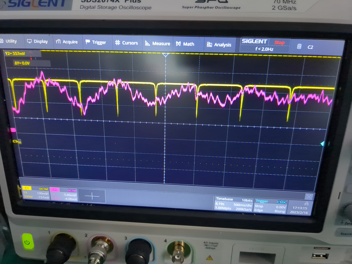
Oscilloscope picture showing the strong Ar I line at 1409.36nm.
Video where the TEC is turned on and off to repeatedly scan over the Ar I line.
Oscilloscope picture of my very first observation of the La III spectrum near 1409.6nm, showing hyperfine structure. The X axis is flipped compared to the figure in the original paper as the optical frequency was decreasing when this picture was taken. Note the oscilloscope's vertical scale: 5mV/div compared to 500mV/div in the pictures above for Ar I. The La III signal is two orders of magnitude weaker than the Ar I signal! The signal-to-noise ratio is not great but there are probably low-hanging fruits.
More to come later!
All amounts are in U.S. dollars and approximative. Not included are common electronic lab equipment (oscilloscope, DC power supplies, soldering iron, function generator), fusion splicing kit (can be as low as $600 for Chinese models), and laser safety glasses. If you are starting from zero, the MHS5200A function generator is very low-cost ($50) and definitely capable. If you want it really cheap, replacing the MEMS VOA with a homemade mechanical chopper built from scrap and sampling the beam with a Fresnel reflection from a microscope slide is likely feasible, and all mechanical mounts could be homemade from scrap as well (the alignment is not very critical). The polarization controller is also somewhat optional - manually bending and taping the fiber around also works, though it is time-consuming, fiddly and tedious.
| CWDM DFB laser | $200 (one wavelength) |
| Hollow cathode lamp | $350 |
| MEMS VOA | $170 |
| Polarization controller | $70 |
| Fiber splitters | 3*$10=$30 |
| Collimation lens | $10 |
| Photodiodes | 2*$5=$10 |
| Optical breadboard, mounts, mirrors | $250 (varies) |
| AD630 lock-in amplifier | $50 |
| VFL | $10 |
| Total | $1,150 |
Thanks to David Allcock and Steven Olmschenk for productive discussions about this experiment.
Thanks to Samuel Goldwasser, Rüdiger Paschotta, and Alexandra Elbakyan for making educational literature available.