July 2023
With the exception of the venerable 633nm HeNe laser (equipped with simple stabilization electronics and polarizing filter), single-frequency lasers with linewidths below ~100kHz are uncommon and often very expensive. For example, the grossly overpriced proprietary ECDL found in modern atomic physics labs can exhibit a free-running linewidth over a hundred kHz, and often requires external reduction of its linewidth using a complicated electronic servo, an expensive reference cavity, and a small army of postdocs to keep it aligned.
Surprisingly, ordinary optical fiber that costs less per meter than toilet paper can be optically pumped, exhibit narrow-band and homogeneously broadened gain, and serve as the medium for the realization of a very narrow (few kHz) linewidth laser, thanks to a phenomenon known as stimulated Brillouin scattering. The best study of this type of laser that I have found is Alain Küng's excellent PhD thesis (in French), which provides a clear and detailed quantitative analysis with practical examples and realizations. The main difficulty with this type of laser is that the pump light must already have a pretty narrow (~MHz) bandwidth, so pumping with FP diodes (without external cavities) to reach interesting spectroscopic wavelengths sounds challenging. Nevertheless, Brillouin gain remains easy to observe and experiment with using single-frequency telecom DFB diodes, and a stimulated Brillouin scattering (SBS) laser is easy to construct.
According to the literature, the SBS process can amplify a signal about 10GHz red-detuned from the pump. To obtain the required pump and signal frequencies, two identical Eudyna FLD5F15CX-H DFB diodes are wired in series so they experience the same current, and then the pump's TEC is turned on with the polarity for cooling (in DFB datasheets, this usually corresponds to the polarity indicated by the plus and minus signs on the laser pinout) to increase the pump's frequency, or, alternatively, the signal's TEC is turned on with the polarity for heating.
The two lasers are sent in opposite directions into a 75m coil of single-mode telecom fiber using two circulators, as shown on the figure below:
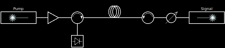
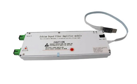
The first circulator injects the pump light and separates the signal light to send it into a photodiode. The EDFA in the pump path is optional, but the SBS effect is more dramatic at high pump intensities. The second circulator is used as an isolator to prevent the pump laser from destabilizing or damaging the signal laser. The built-in isolator of DFB packages is not enough and only prevents laser instability up to injected powers of some dozen microwatts! Since we want more pump power than signal power, a manual variable optical attenuator (VOA) is inserted after the signal DFB to reduce the laser power sent into the fiber coil.
Cost-effective 1550nm fiber-coupled circulators can be obtained from Shenzhen Box Optronics and many other telecom suppliers. Despite their claims of decades of experience and their brandishing of patents (some of them expired), the 1550nm fiber-coupled circulators manufactured by a famous U.S. scientific supplier are literally 10x more expensive and do not have better optical specs.
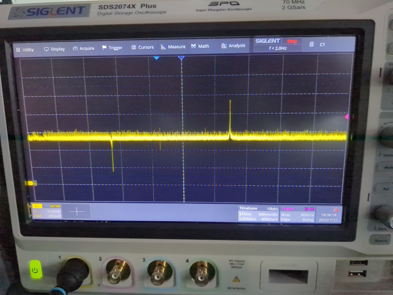
When the laser pump frequency is ramped up by cooling it (or, alternatively, the signal frequency is ramped down), a peak of amplification can be seen at the photodiode output! From subjective experience with fiber ring resonators connected to thermally frequency-sweeped DFBs, the width of the gain peak appears consistent with a bandwidth of some dozen MHz, as reported in Alain Küng's thesis.
Unexplained features of the plot include a high background noise that increases with the intensity of the pump and is present even without the signal laser (Brillouin ASE noise?), a peak of absorption (the system working in reverse - signal laser causing SBS amplification of the pump? the two DFBs are not strictly identical and could easily start with >10GHz of detuning from manufacturing tolerances), and some disturbance somewhat in the middle (the two lasers having the same frequency?). But, in any case, plenty of gain is clearly observable!
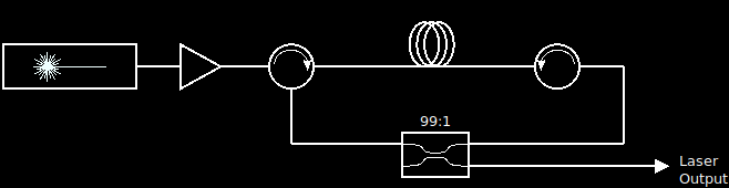
Replacing the signal laser with the SBS output from the first circulator and tapping into the cavity light with a 99:1 FBT splitter (as shown on the figure below) produced an output power of 2.6mW with 150mW of pump light. Clearly, the fiber was lasing, since the 2.6mW at the output of the splitter meant that 260mW was circulating into the ring, and the power output was relatively stable despite DFB frequency fluctuations that could be induced by passing current into the TEC. Only a laser resonance could result in this!
The linewidth of the emitted laser light was determined using a conventional self-heterodyne measurement technique with an all-fiber setup using a pair of PLC splitters from FS.com, a 10km spool of fiber, and a fiber-coupled AOM.
The photodiode is connected directly to a bladeRF software defined radio, with the integrated bias-tee turned on (the trick is to create a file ~/bladerf.conf containing the line "biastee_rx on") and biased in reverse from the bladeRF's DC output voltage. Incorrect polarity will likely destroy the photodiode. To make it foolproof, you can add a series current-limiting resistor with an AC bypass capacitor in parallel with the resistor, which should remove this risk. The Gqrx program can then be used to display the spectrum. Make sure to use the libbladeRF frontend directly without the SoapySDR layer, which has some bugs and missing features.
AOMs are not cheap components, and the lower-priced ones seem to be available from CASTECH and CSRayzer. They will set you back around 1000 USD. Unfortunately it is difficult to make a reliable measurement of a single laser without one, due to the high levels of noise near DC. If you want to avoid the AOM without sacrificing measurement quality, you may be able to offset-lock two DFBs using the other bladeRF RX channel, a computer-controlled TEC driver (Rigol DP832 might be enough its noise is too high and its firmware will eventually crash as you hammer it with frequent current change commands) and some Python/Numpy scripting. You would then use those two offset beams to pump independent SBS lasers and measure their beat note. I have not attempted this offset lock scheme with DFB lasers, only HeNe with a small homemade induction heater on the tube's metallic mirror mount, but I'm pretty sure that it would still work. From a quick experiment the frequency of DFB modules without external stabilization seem to be stable enough at 100ms timescales so a simple software-based control loop in Python may be enough despite its low update rate and high latency.
The AOM is driven directly with a RF generator that puts out just 40mW at 80MHz. The AOM's diffraction efficiency is of course very low at such drive levels, but this avoids the complications associated with dealing with several watts of RF, in particular the risk of damaging the expensive AOM if its maximum RF power level is exceeded. Since we have plenty of laser power to work with, and heterodyne gain from the other, unattenuated arm of the interferometer, this works well enough. By inserting the AOM before the fiber delay line, the attenuation provided by the AOM also has the advantage of suppressing Brillouin scattering from the long fiber spool which, when sent back into the laser, could destabilize it (this problem was actually my first encounter with Brillouin scattering, while attempting to measure the linewidth of a DFB diode).
The linewidth measurement of the first laser revealed strong multimode operation with many narrow peaks. This laser was thus improved in several ways:
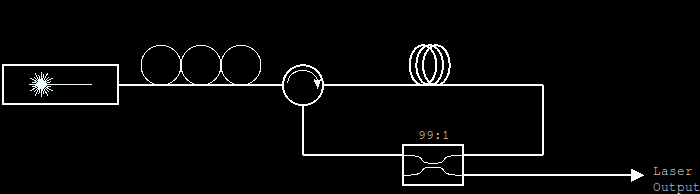
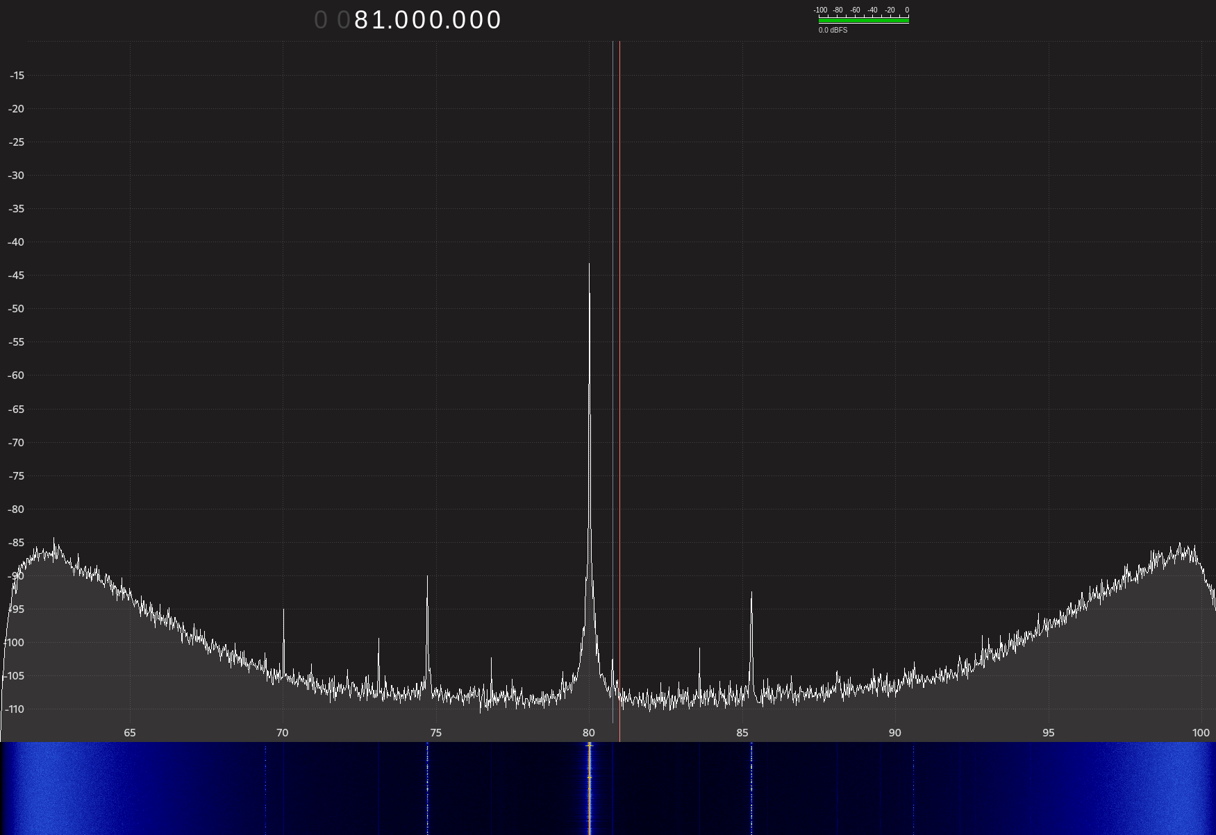
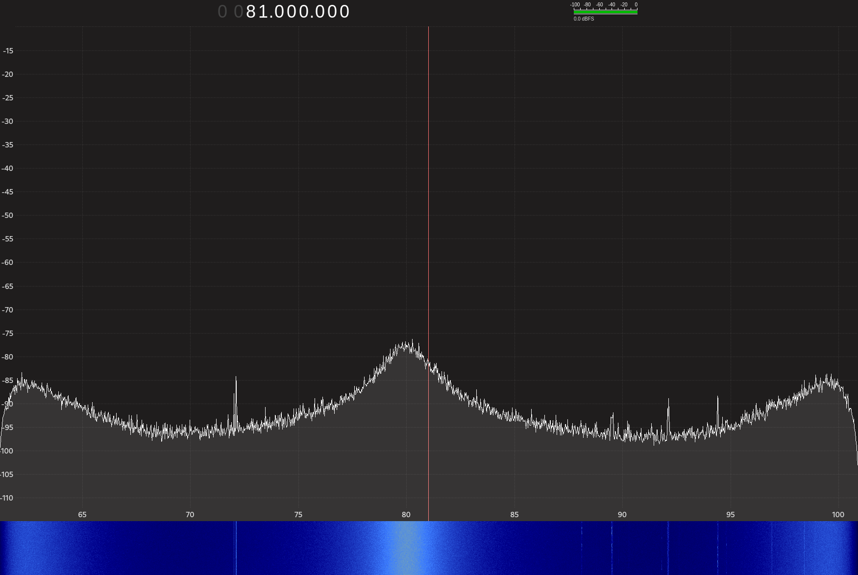
With those modifications, the laser is mostly single-frequency and narrow-linewidth, as shown on this Gqrx screenshot. The two lobes of noise on the sides are an artifact of the bladeRF's transceiver chip, and the solid lines at frequencies other than 80MHz are some RF pickup that remains present with the laser off. There are still some low-intensity spurious modes that appear intermittently, and may be related to mode sweeping - the pump DFB was not stabilized at all and its frequency on a ~1s timescale was fluctuating well above the FSR of the SBS laser resonator. Locking the DFB's wavelength to a HCN spectroscopic cell or just stabilizing its temperature may help, but this will be for another day. Still, this is to be contrasted with the same measurement made on the direct DFB diode's output.
With a fiber delay line of "only" 10km, it is not possible to give an accurate measurement of such a narrow linewidth, though building a recirculating fiber loop with the cheap EDFA sounds feasible. Still, the results appear consistent with the linewidths of a few kHz reported in the literature. Some papers will claim a linewidth of a few dozen Hz for this type of laser, but upon reading the details this is only valid for the linewidth of the beat note of two resonances occuring in the same laser cavity and therefore subject to the same external disturbances. At this level of precision, vibrations and other environmental disturbances have a major effect on the optical frequency fluctuations, as demonstrated in the video: Laser linewidth vs. Queen. To reach dozens Hertz of linewidth without an external servo mechanism, the laser cavity needs to have a level of mechanical stability that a mere coil of fiber simply cannot provide. Nevertheless, even with acoustic vibration levels normally not found in a physics lab, the SBS laser keeps its linewidth below that of a pricy and finicky ECDL.
> Towards stabilization of the SBS laser
< Table of Contents