September 2023
The previous experiment demonstrated a low-cost laser with an impressively narrow instantaneous linewidth. Yet, it isn't very stable: it is affected by significant amplitude noise, mode hops, and low-intensity side modes that would appear briefly and randomly.
We can try to understand what is going on if we consider that the pump laser is not stabilized at all and its output is therefore affected by optical frequency noise on the order of hundreds of MHz (on top of its 5-10MHz instantaneous linewidth, which is narrower than the Brillouin gain bandwidth and unlikely to be the issue here). One can expect those noisy fluctuations to be transferred to the Brillouin gain curve. Those fluctuations are at least one order of magnitude greater than the FSR of the fiber cavity. Therefore, the gain experienced by the lasing mode is fluctuating, the mode that gets selected for lasing is constantly changing, and the laser may randomly cross into multi-mode regions. This is illustrated by the following diagram:
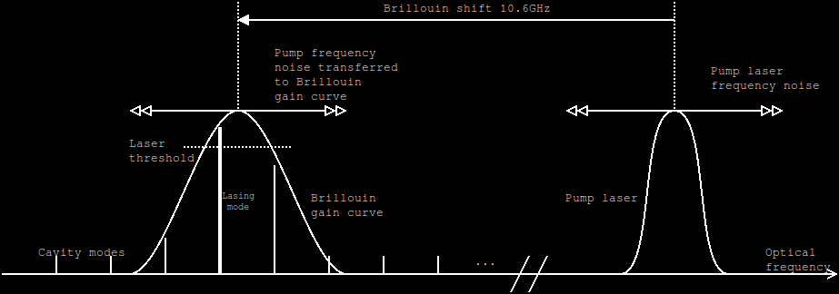
If we assume that the Brillouin shift is constant, this gives us a way to measure the position of the lasing mode with respect to the Brillouin gain peak, and correct the frequency of the pump laser to keep the lasing mode at the same position within the gain curve (preferably near the peak). Indeed, we can heterodyne the pump laser with the output of the SBS laser, and obtain a RF signal at the Brillouin shift frequency (around 10GHz) detuned by the difference between the lasing cavity mode and the Brillouin gain peak (neglecting any frequency-pulling effects).
Photodetectors for laboratory purposes with over 10GHz of bandwidth are, as usual, ridiculously priced and yet another opportunity for pen-pushers to waste your time with end user certificates and other Kafkian procedures. It is also difficult to build one with inexpensive equipment, since the capacitance at the TIA input needs to be minimized to a level that typically requires wire-bonding between the bare dies of the photodiode and TIA chip. The trick is to butcher a 25-gigabit Ethernet optical SFP (available inexpensively from FS.com, Gigalight, and others) and make use of its internal high-speed optical receiver. Simply using the standard SFP data output does not sound like a good option. We want to look at the raw analog signal before the limiting amplifier which would destroy information, particularly in the case of 25G devices which also contain a CDR and equalizer.
The supply chain for those SFPs appears to be a bit of a insiders' club, since it is basically impossible to buy separately the photodiode/TIA module (called "ROSA" in manufacturer jargon) and in most cases obtain any documentation about it. Both SFPs I disassembled from FS and Gigalight were built around two different ICs from MACOM with part numbers that are not listed on the MACOM website (and those that are listed do not have public datasheets). Emails were of course ignored after I told them that I just wanted to experiment with a SFP. The SFP laser modules ("TOSA") are similarly undocumented and impossible to buy separately.
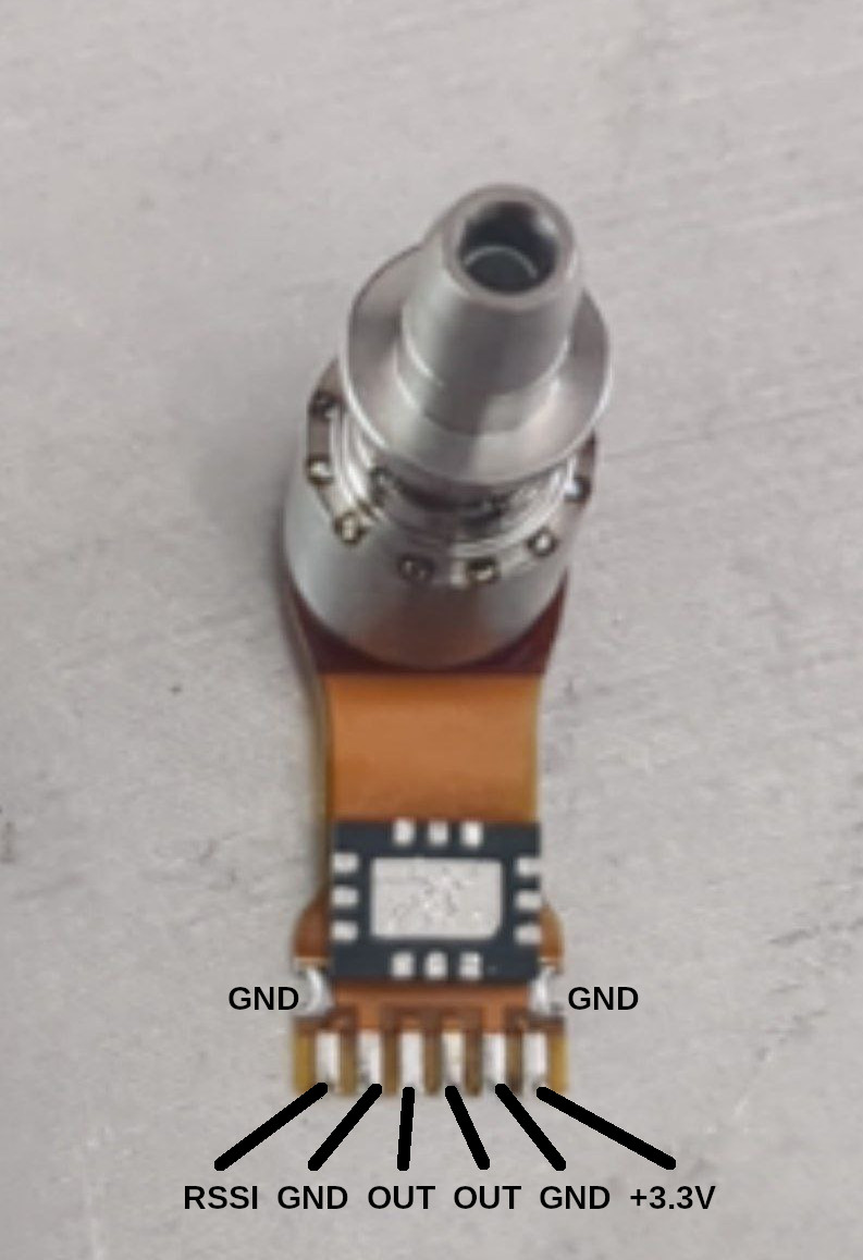
Fortunately, it is not very difficult to figure out how to use an undocumented ROSA (or a TOSA, but this will be for another article). It will typically connect to the SFP's main PCB using a small flexible printed circuit with several solder pins. Several of these pins are ground and can be identified by looking at the printed circuit layouts and/or checking for a low-impedance path with the ground pins at the (standard) SFP connector using a DC multimeter. The main output can be clearly identified by the differential transmission line pattern on the SFP's main PCB. This usually leaves only two pins, which are RSSI and the power input. They can be identified, and the correct ROSA supply voltage determined, by measuring the voltage at those pins with the SFP operating with and without an optical input signal. Tracing the PCB can be difficult due to the frequent use of via-in-pad and blind vias in those miniaturized devices. For reference, here is the appearance and pinout of the FS.com 25G ROSA (with a MTX2-183+ glued on the flex PCB, not part of the original SFP). The normal current draw is around 25mA.
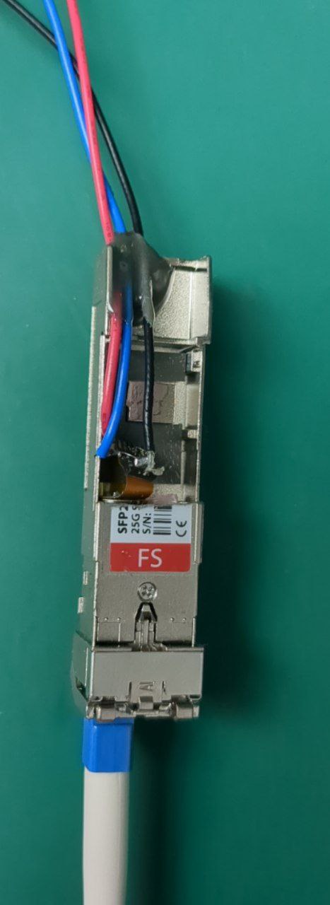
The output pins of the ROSA were connected to a MTX2-183+ balun transformer to adapt the differential signal to a 50-ohm coaxial connection compatible with standard RF equipment. You may be able to use baluns that are easier to obtain and cheaper than the MTX2-183+ - I chose it because of its particularly broad bandwidth, as the literature about the exact value of the Brillouin shift in fibers is somewhat contradictory and I wanted to be able to search for the Brillouin heterodyne signal in as much RF spectrum as practically possible. It is important to AC-couple the MTX2-183+ using two capacitors, as both pins of the ROSA have a DC bias that the MTX2-183+ would short-circuit to ground, potentially resulting in permanent damage. Take note that the center point of the secondary of the MTX2-183+ is grounded. This had escaped me during the first attempt at building this circuit, and I immediately noticed that something was wrong as the ROSA was drawing an unreasonable current. Luckily, I switched it off and investigated before any damage was done. Since I didn't have any capacitors on hand that I knew would work over 10GHz, I desoldered the original coupling capacitors from the SFP and used that. Those were 0201 SMD capacitors, which made for a tedious and cosmetically questionable soldering job, with the capacitors hanging in mid-air with one pin soldered to the MTX2-183+ and the other connected to the flex printed circuit with a fine copper wire. You may want to plan things better, try to use bigger capacitors, and perhaps even spin a small custom PCB. The primary of the MTX2-183+, on the other hand, is internally AC-coupled as per the "Marchand balun" design commonly used as such high frequencies. So you will not be able to check the coax connection with a DC multimeter. One last thing to be careful about is that some pins marked "NC" in the MTX2-183+ datasheet are in reality connected to ground.
The original cover of the SFP was cut in half with a dremel to leave space for the balun/coax hack-job and the 3.3V power cables, and the part that holds the ROSA and fiber connector screwed back in place. The end result is not particularly beautiful, and that SFP's warranty was definitely voided, but it is functional.
The 50-ohm output of the ROSA was downconverted using a HMC412-based mixer module (Aliexpress) with the IF output feeding a bladeRF software-defined radio. The LO input of the mixer was driven using the doubled output of a low-cost ADF5355-based RF generator from Aliexpress, with an amplifier ("2-18G Broadband LNA" from TGCHR Store) to meet the LO power requirements of the HMC412.
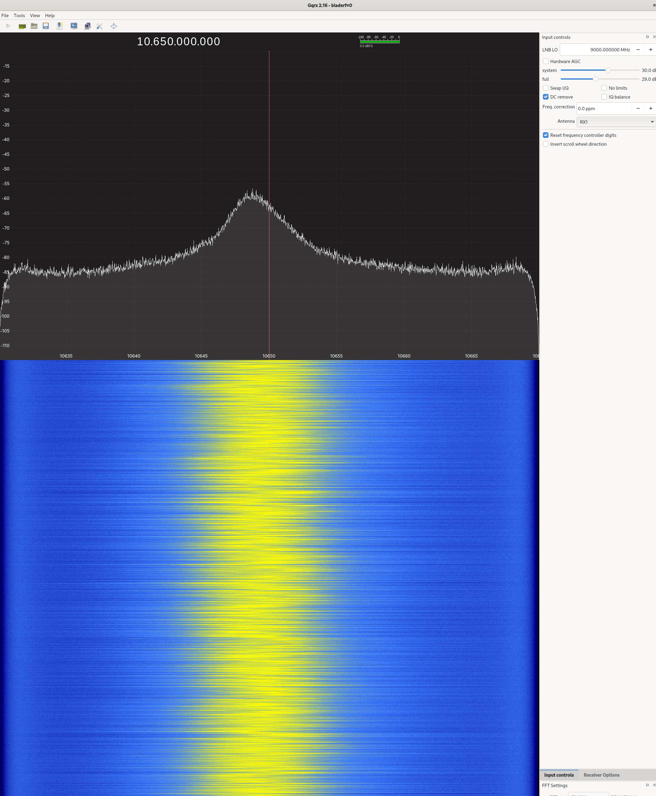
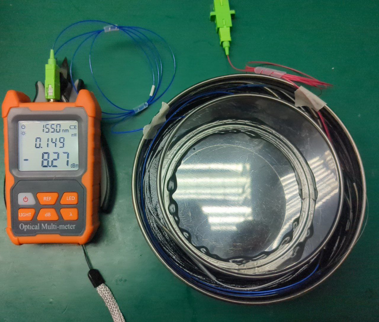
With the RF generator set to 9000MHz, and the bladeRF set to 1650MHz in Gqrx, a strong signal was visible near the middle of the waterfall display, corresponding to a Brillouin shift around 10.6GHz. It was quite satisfying to be able to measure this, when every other setup in the literature appears to cost as much as a sports car :)
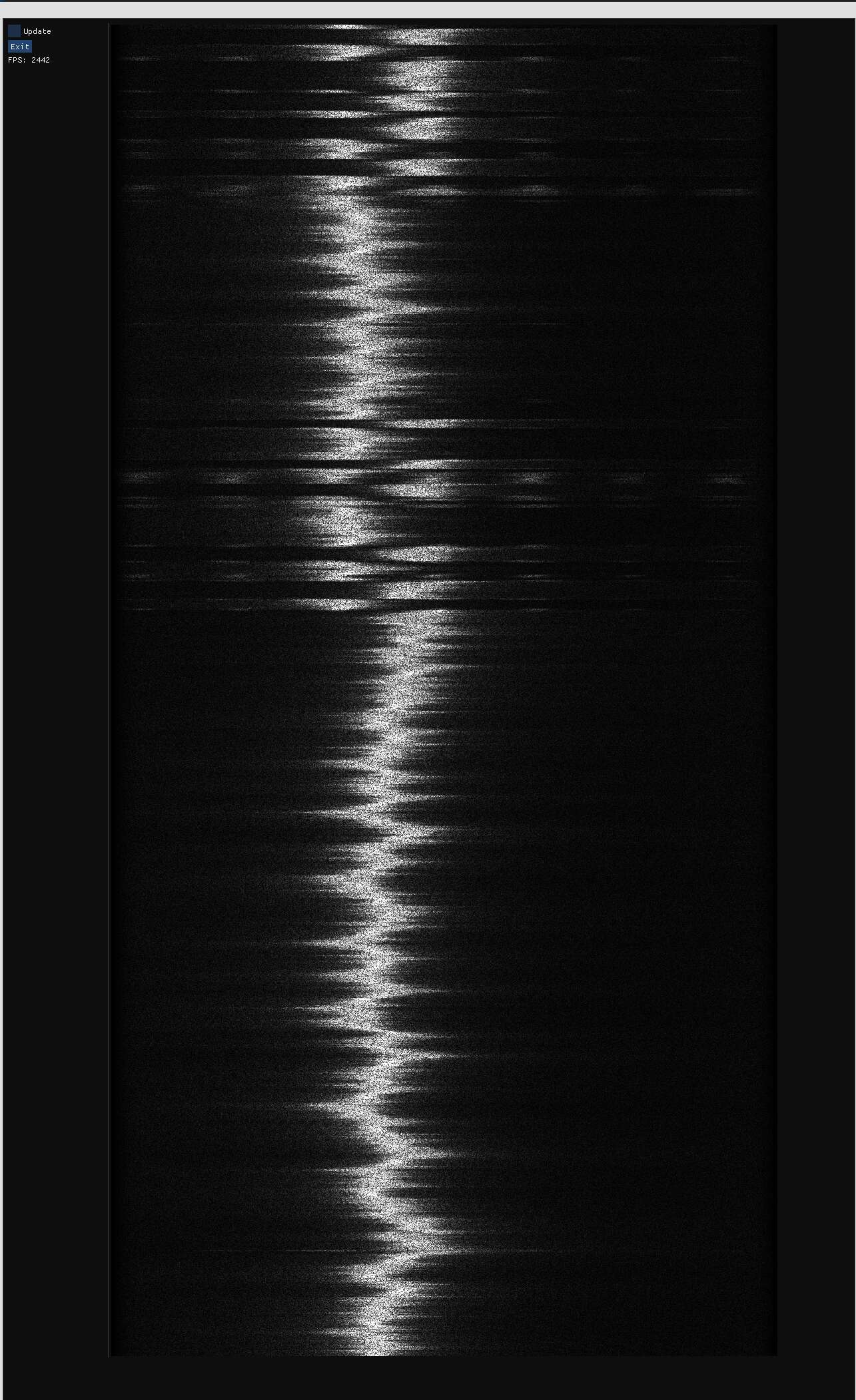
The signal also appeared to show some evidence of the mode-sweeping/mode-hopping behavior theorized above, though at the speed at which it would be happening, it was difficult to draw any conclusions due to Gqrx's cap at 60 frames per second even when small Fourier transform sizes are selected. Therefore, a basic alternative program with no arbitrary FPS limit was developed using libbladeRF, PocketFFT for C++, GLFW and dear imgui. This produced a much clearer picture and stronger support for the theory. Indeed, it became apparent that the SBS laser would mode-hop when and only when the heterodyne frequency was near its minimum or maximum value.
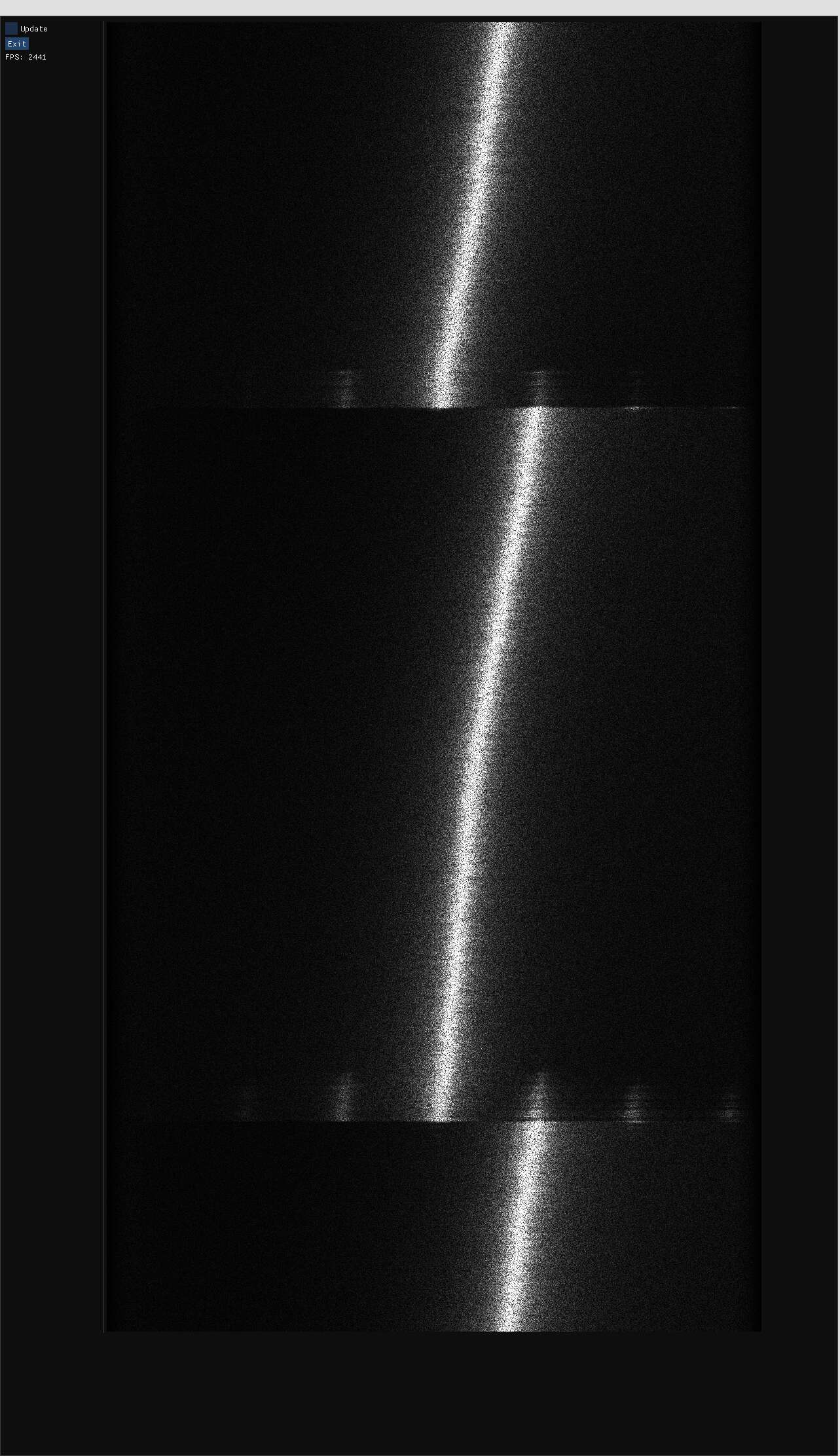
Microphonics were reduced by potting the fiber cavity in epoxy resin, making a kind of a "fiber cake". You may want to use clear resin (unlike what I did) so that any major problems inside the potted volume can be found with a VFL. Stabilizing the pump laser's temperature to the millikelvin level using a Sinara 8451 thermostat connected to the butterfly package's TEC and thermistor produced a minor improvement in stability. The last source of technical noise to investigate was the laser diode's power supply, which was simply a Rigol DP832 in constant voltage mode with a series resistor. The Rigol unit was replaced with two 3000F 2.7V ultracapacitors connected in series to increase the maximum permissible voltage. I was rewarded with this fantastic plot of the SBS laser mode-sweeping as the capacitors discharged (virtually noiselessly) and the pump laser's optical frequency varied accordingly, confirming the theory above and pinpointing the origin of the noise that was causing the instabilities we had seen.
A small amount of frequency pulling is also apparent as the lines are not completely straight and slightly bend in the middle (try this).
This mode-sweep plot also tells us what current noise level is acceptable for driving the pump laser diode. We can see that one cycle of mode-sweeping takes 450ms. This is with a laser current of 150mA, a series resistor of 11 ohm and 1500F of capacitance. Assuming constant voltage across the laser diode, this corresponds to an estimated current drop of 4 microamperes per mode-sweep cycle. The conclusions of this experiment are: A proper driver for SBS pump laser diodes should exhibit noise significantly below that, and the laser control system would be able to detect instability regions and operate the SBS laser away from them by looking at the pump/output heterodyne signal and servoing on the pump laser current or temperature.
> Stabilization of the SBS laser
< Table of Contents